www.beyma.com
Notes
:
* The power capaticty is determined according to AES2-1984 (r2003) standard. Program
power is defined as the transducer’s ability to handle normal music program material.
** T-S parameters are measured after an exercise period using a preconditioning power test.
The measurements are carried out with a velocity-current laser transducer and will reflect the
long term parameters (once the loudspeaker has been working for a short period of time).
*** The Xmax is calculated as (Lvc - Hag)/2 + (Hag/3,5), where Lvc is the voice coil length and
Hag is the air gap height.
Nominal diameter
Rated impedance
Minimum impedance
Power capacity*
Program power
Sensitivity
Frequency range
Recom. enclosure vol.
Voice coil diameter
Magnetic assembly weight
Bl factor
Moving mass
Voice coil length
Air gap height
X
damage
(peak to peak)
540 mm 21 in
8 Ω
5,4 Ω
1.400 W
AES
2.800 W
98,5 dB @ 1W @ Z
N
25 - 1.800 Hz
100 / 250 l 3,5 / 8,75 ft
3
100 mm 4 in
14,4 kg 31,8 lb
28,2 N/A
0,298 kg
25 mm
12 mm
55 mm
Overall diameter
Bolt circle diameter
Baffle cutout diameter:
- Front mount
- Rear mount
Depth
Volume displaced by driver
Net weight
Shipping weight
550 mm 21,65 in
526 mm 20,71 in
494 mm 19,45 in
511 mm 20,12 in
242 mm 9,53 in
20 l 0,71 ft
3
19,9 kg 43,87 lb
22,6 kg 50,0 lb
KEY FEATURES
THIELE-SMALL PARAMETERS**
TECHNICAL SPECIFICATIONS
MOUNTING INFORMATION
DIMENSION DRAWINGS
Resonant frequency, f
s
D.C. Voice coil resistance, R
e
Mechanical Quality Factor, Q
ms
Electrical Quality Factor, Q
es
Total Quality Factor, Q
ts
Equivalent Air Volume to C
ms
, V
as
Mechanical Compliance, C
ms
Mechanical Resistance, R
ms
Efficiency, η
0
Effective Surface Area, S
d
Maximum Displacement, X
max
***
Displacement Volume, V
d
Voice Coil Inductance, L
e
30 Hz
5,2 Ω
7,44
0,36
0,34
401,5 l
94
µ
m / N
7,51 kg / s
2,83 %
0,1734 m
2
10 mm
1.729 cm
3
1,3 mH
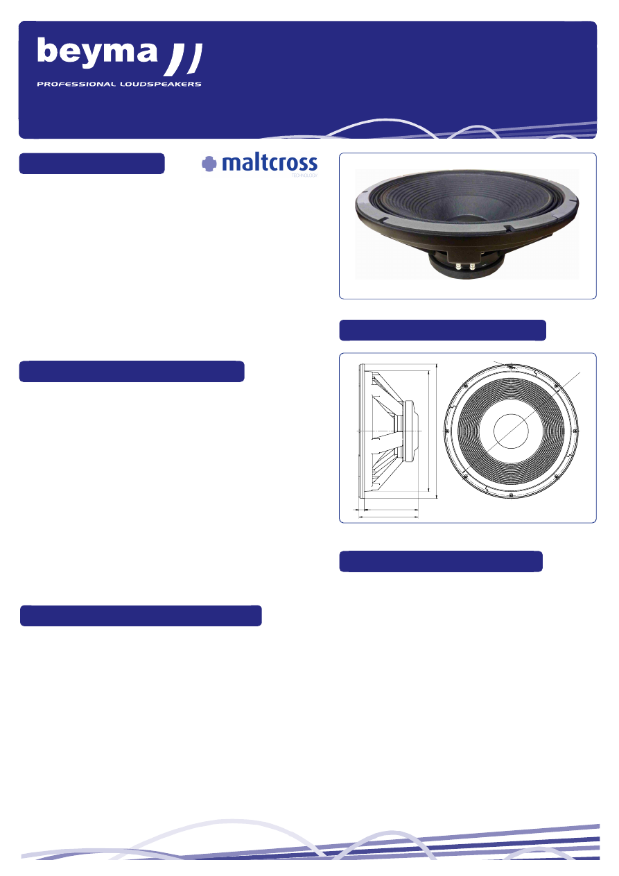
21PW1400/Fe
LOW FREQUENCY TRANSDUCER
PW Series
● High power handling: 1400 W
AES
● Malt Cross
®
Cooling System
● Low power compression looses
● High sensitivity: 98,5 dB
● FEA optimized ferrite magnetic circuit
● Designed with MMSS technology for high control, linearity and
low harmonic distortion
● Optimized nonlinear parameters
● Waterproof cone with treatment for both sides of the cone
● 4” DUO double layer inner/outer voice coil
● Aluminium demodulating ring
● Extended controlled displacement: X
max
± 10 mm
● Massive mechanical displacement capability: X
damage
± 55 mm