Страница 3 из 41 1. Introduction 1.1 Safety instruction The UPS must be installed and maintained exclusively by quailified staff. See installation and operation instructions before connecting to the supply. The UPS must be installed with an earth connection. It has a high leakage current. The first wire to be
Страница 4 из 41 All battery installation and maintenance operations entail gaining access to the inside of the UPS and require the use of tools: these operations are to be performed exclusively by qualified staff. The batteries replaced are to be considered as toxic waste and treated accordingly. Dispose of used
Страница 6 из 41 1.3 Special Symbols The following are examples of symbols used on the UPS or accessories to show you the important information: 4
Страница 7 из 41 2.Presentation 9E series UPS uses ON-LINE double conversion technology, resulting in the highest levels of reliability and maximum protection for critical loads. 2.1 Model List Model Power Ratings PF Voltage (Output) 9E6Ki 6kVA/4.8kW 0.8 230V (220/240) 9E10Ki 10kVA/8kW Combo 0.8 230V (220/240)
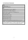
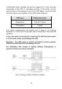
Страница 8 из 41 9E10Ki, 9E10KiXL Main power wiring Bypass ` Input Switch L1 Maintain Switch L2 Input filter INPUT L3 Output filter AC/DC—DC/AC N N Output Switch OUTPUT L Internal power Charger Battery 9E15Ki, 9E20Ki, 9E20KiXL Main power wiring Bypass ` Input Switch L1 Maintain Switch L2 Input filter INPUT L3 AC-DC
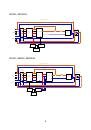
Страница 9 из 41 2.3 UPS views 2.3.1 UPS Front view ① Display ② Multipurpose buttons ③ Wheels (front wheels swivel and can be locked, fixed rear wheels) 7
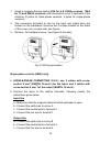
Страница 10 из 41 2.3.2 UPS Rear view 9E6Ki With backpanel cover 9E6Ki Without backpanel cover ④ USB communication port ⑩ Input switch RS232 communication port Slot for optional ⑥ communication card ⑪ Cover for terminals ⑫ Fuse ⑦ Cooling fan(s) ⑬ ⑧ Output switch ⑭ Earthing screws ⑮ Tie wrap hold-down ⑤ ⑨ Manual
Страница 11 из 41 ④ USB communication port ⑩ Input switch RS232 communication port Slot for optional ⑥ communication card ⑪ Cover for terminals ⑫ Fuse ⑦ Cooling fan(s) ⑬ ⑧ Output switch ⑭ Earthing screws ⑮ Tie wrap hold-down ⑤ ⑨ Manual bypass for maintenance 9 Terminals for I/O cable connection (refer to related
Страница 12 из 41 UPS Rear view 9E15Ki/9E15KiXL/9E20Ki/9E20KiXL 9E15Ki/9E15KiXL/9E20Ki/9E20KiXL With backpanel cover Without backpanel cover ④ RS232 communication port ⑩ Input switch ⑤ USB communication port ⑪ Cover for terminals ⑥ Slot for optional communication card ⑫ Terminals for I/O cable connection (refer to
Страница 13 из 41 2.3.3 EBM Rear view ① Fuse ② Cover for terminals ③ Tie wrap hold-down ④ Wheels (front wheels swivel and can be locked, fixed rear wheels) ⑤ Terminals for I/O cable connection (refer to related section) ⑥ Earthing screws 11
Страница 14 из 41 3.Installation 3.1 Unpacking 1. Cut the straps 2. Open the carton, take off wood board, accessory pack and PE form. 3. Remove carton upward and take out front PE form. 4. Put the wood board (removed at step2) as figure showed. Make sure that the slide rests firmly against the pallet so it remains
Страница 15 из 41 3.2 Package content After opening the packaging, it is first necessary to check the contents. The package must contain: UPS USB cable RS232 cable Jumper (15/20kVA models only) User manual Software CD 3.3 Connection 3.3.1 Installation requirements Warning: Installation must be performed by qualified
Страница 16 из 41 A differential switch upstream will also be triggered for a fault occurring downstream of the UPS. In calculating reactivity of this switch, account must be taken of the leakage current of the UPS (approx. 8 mA) plus that of the load which come together on the UPS’s earth conductor. UPS input
Страница 17 из 41 Notice: It is required to install an external isolating device against current backfeed between Mains input and UPS. After the device is installed, it must add a warning label with the following wording or the equivalent on the external AC contactor: RISK OF VOLTAGE BACKFEED. Isolate the UPS before
Страница 18 из 41 1. Install a magneto-thermal switch (63A for 6 & 10kVA versions, 125A for 15 and 20kVA versions) with intervention curve D upstream of the machine (4 poles for three-phase versions, 2 poles for single-phase versions). 2. The connection terminals to use for the input and output lines are located on
Страница 19 из 41 R.E.P.O. a - The REPO connection (between terminal 5 and 6) is normally open. For more information please refer to the REPO section of this manual Fig.3-4 6K terminal view 6. Tighten the terminals well, close the backpanel cover and secure it with the screws taken out earlier. The suggested tighten
Страница 20 из 41 5. Short-circuit the input terminals (1, 2 and 3) with the jumper provided in the accessories kit. Connect the wires to the respective terminals, following exactly the instructions below: Input line a - Ensure that the upstream magneto-thermal switch is open. b - Connect the earth wire to screw A.
Страница 21 из 41 Three-phase connection 1. (THREE-PHASE CONNECTION 9E10KI, 9E10KIXL): Use 2 cables of 2 2 cross-section 4 mm (L2 and L3) and 3 with cross-section 10 mm (EARTH, N, L1) for the input (N.B.: L1 and N are of greater crosssection because in bypass operation they have to carry all of the 2 input current).
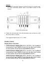
Страница 22 из 41 Fig.3-6 10~20K three phase input terminal view 3. Tighten the terminals well, close the backpanel cover and secure it with the screws taken out earlier. For 10 to 15kVA the suggested tighten force is 1.2~1.6Nm. For 20kVA, the suggested tighten force is 2.5~3 Nm. R.E.P.O. The terminal block on the
Страница 23 из 41 2 1. Use a 2x0.75mm cable to make the connection with the R.E.P.O. terminals. 2. Insert the screw driver in the square hole and press down to make the round hole terminal open. Then insert the wire into the round hole. Then pull out the screw driver. Connect the two wires of the cable to terminals
Страница 24 из 41 3.3.3 EBM Wiring Connection It is possible to connect more than one EBM in order to achieve any level of autonomy without mains power. In order to ensure the battery runtime displayed is accurate, please set your battery configuration through UPS Configuration Tool (download available here:
Страница 25 из 41 Versions 9E6Ki, 9E10Ki, 9E10KiXL Fig.3-9 EBM terminal connection for 9E6Ki, 9E10Ki, 9E10KiXL With Single EBM Fig.3-10 EBM terminal connection for 9E6Ki, 9E10Ki, 9E10KiXL With Mutliple EBM Note: For 9E15Ki, 9E20Ki, 9E20KiXL EBM wiring connection, you should check the 9EEBM manual in EBM package. 23
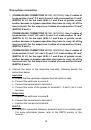
Страница 26 из 41 4.OPERATION 4.1 Display and Buttons Fig. 4-1 Control Panel The following tables shows the buttons, LCD indicator and LED indicator status and description: Table 4-1 Control Buttons Functions The Button Function Turn on Turn off Transfer Illustration If the UPS is in standby or bypass mode, press
Страница 27 из 41 Table 4-2 LED indicator LED name Colour Description Line Green It indicates the utility is normal Battery Yellow It indicates the input is connected with battery, and the input power is supplied from the battery. Bypass Yellow It indicates the UPS is in bypass mode, the load current is directly
Страница 28 из 41 Table 4-3 Buzzer Priority UPS condition Buzzer 1 UPS fault and failure Continuous 2 Normal mode No beep 3 Battery/battery test mode One beep per 4 sec (One beep per 1s when battery low) 4 Bypass mode One beep per 2 minutes 5 Overload One beep per 500ms 6 Other alarm One beep per 1s 7 Manual bypass
Страница 29 из 41 Icon Icon name Description Measureme nts Display values, eg: voltage, frequency, load percentage, etc. DC Voltage Percentage Output Input Load Battery voltage The percentage, eg: Load percentage and battery capacity percentage It indicates information for output. It indicates information for input.
Страница 30 из 41 4.2 Operating UPS Notice: Please switch off the connected loads first before turning on the UPS, and switch on the loads one by one after the UPS is turned on. Switch off all of the connected loads before turning off the UPS. Notice: Power on for the first time 1. Close the magnetothermic switch
Страница 31 из 41 4.2.4 Turning off UPS without mains To power off the UPS press button continuously for more than 3s, and the buzzer beep once. The UPS will cut off the output. A few seconds later, LCD shuts down and no voltage is available from the UPS output. 4.2.5 Transfer to Bypass To transfer the UPS in
Страница 32 из 41 4.3 Configuration 4.3.1 UPS parameters In order to change UPS parameters (Output Voltage, Number of EBM, ....) please use UPS Configuration Tool (download available here: http://pqsoftware.eaton.com). 4.3.2 Communication ports On the back of the UPS (see UPS Views), the following communication
Страница 33 из 41 Connectivity Cards The UPS is equipped with an expansion slot for optional Connectivity Cards (see figure on right). It is not necessary to shutdown the UPS before installing a communication card. 1. Remove the slot cover secured by screws. 2. Insert the communication card in the slot. 3. Secure
Страница 34 из 41 Each 9E UPS ships with Eaton Intelligent Power Software suite. To begin installing, see the instructions accompanying the Software suite CD. Eaton Software suite provides up-to-date graphics of UPS power and system data and power flow. It also gives you a complete record of critical power events,
Страница 35 из 41 THE BUZZER SOUNDS CONTINUOUSLY THE LOAD AND THE DISPLAY APPLIED TO THE SHOWS ONE OF THE UPS IS TOO HIGH FOLLOWING CODES: A80E, A810, F808 BATTERIES THE DISPLAY MISSING OR SHOWS THE BATTERY BOX FOLLOW CODE: MISSING OR NOT A60D CONNECTED THE BUZZER SOUNDS THE CONTINUOUSLY TEMPERATURE AND THE DISPLAY
Страница 36 из 41 4.5 Alarm codes Using a sophisticated self-diagnosis system, the UPS is able to check its own status and any anomalies and/or faults which may occur during normal operation and display them on the display panel. If there is a problem, the UPS signals the event by showing the code and the type of
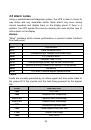
Страница 37 из 41 F704 Failed inverter soft start F70C Inverter undervoltage F808 Output overload fault F811 Negative output power 5.Technical data UPS MODELS 9E10Ki, 9E10KiXL 9E6Ki 9E15Ki 9E20Ki, 9E20KiXL INPUT Nominal voltage [Vac] Maximum operating voltage [Vac] Nominal frequency [Hz] Nominal current BATTERY
Страница 38 из 41 Bypass line not available: locks after 10 s Bypass line available: after 100 ms, then activates the bypass Overload load > 150% locks after 1 s Bypass line not available: OTHER Leakage current to earth Ambient temperature locks after 1 s [mA] < 8mA [°C] 0 – 40 Humidity < 95% without condensation