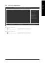
Страница 9 из 89 1-1 English Chapter 1 Hardware Installation Considerations Prior to Installation Preparing Your Computer The motherboard contains numerous delicate electronic circuits and components which can become damaged as a result of electrostatic discharge (ESD). Thus, prior to installation, please follow
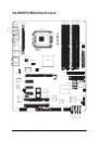
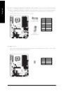
Страница 10 из 89 English 1-2 Feature Summary CPU Chipset Memory Slots IDE Connections FDD Connections Onboard SATA Peripherals Onboard VGA Onboard LAN Onboard Audio Supports the latest Intel ® Pentium® 4 LGA775 CPU Supports 800/533MHz FSB L2 cache varies with CPU Northbridge: Intel® 915G Express Chipset
Страница 11 из 89 Onboard SATA RAID BIOS Additional Features Overclocking Form Factor IT8712 System voltage detection CPU temperature detection CPU / System / Power fan speed detection CPU warning temperature CPU / System / Power fan failure warning CPU smart fan control Onboard ICH6R chipset - supports data
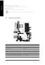
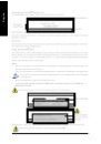
Страница 12 из 89 English 1-3 Installation of the CPU and Heatsink Before installing the CPU, please comply with the following conditions: 1. Please make sure that the motherboard supports the CPU. 2. Please take note of the one indented corner of the CPU. If you install the CPU in the wrong direction, the CPU will
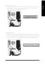
Страница 13 из 89 Male Push Pin The top of Female Push Pin Female Push Pin Fig.1 Please apply an even layer of heatsink paste on the surface of the installed CPU. Fig. 2 (Turning the push pin along the direction of arrow is to remove the heatsink, on the contrary, is to install.) Please note the direction of arrow
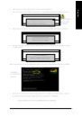
Страница 14 из 89 English 1-4 Installing/Removing Cool-Plus (Northbridge Cooling Fan) Fig.1 To attach Cool-Plus to a heatsink, align the extensions on both sides with the grooves in the heatsink as shown. Firmly press down until it snaps into position. Fig.2 Once the fan is properly affixed onto the heatsink, plug
Страница 15 из 89 Fig.2 Close the plastic clip at both edges of the DIMM sockets to lock the DIMM module. Reverse the installation steps when you wish to remove the DIMM module. Dual Channel DDR II GA-8GNXP-D supports the Dual Channel Technology. After operating the Dual Channel Technology, the bandwidth of Memory
Страница 16 из 89 English 1-6 Installation of Expansion Cards You can install your expansion card by following the steps outlined below: 1. Read the related expansion card's instruction document before install the expansion card into the computer. 2. Remove your computer's chassis cover, screws and slot bracket from
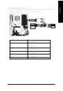
Страница 17 из 89 I/O Back Panel Introduction English 1-7 PS/2 Keyboard and PS/2 Mouse Connector To install a PS/2 port keyboard and mouse, plug the mouse to the upper port (green) and the keyboard to the lower port (purple). Parallel Port The parallel port allows connection of a printer, scanner and other
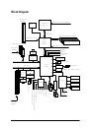
Страница 18 из 89 English Center/Subwoofer Speaker Out Connect the Center/Subwoofer speakers to this connector. Side Speaker Out Connect the side surround speakers to this connector. You can use audio software to configure 2-/4-/6-/8-channel audio functioning. 1-8 Connectors Introduction 1 3 5 2 6 13 8 7 19 20 4 14
Страница 19 из 89 ATX_12V/ATX (Power Connector) With the use of the power connector, the power supply can supply enough stable power to all the components on the motherboard. Before connecting the power connector, please make sure that all components and devices are properly installed. Align the power connector with
Страница 20 из 89 English 3/4/5) CPU_FAN / SYS_FAN / PWR_FAN (Cooler Fan Power Connector) The cooler fan power connector supplies a +12V power voltage via a 3-pin/4-pin(only for CPU_FAN) power connector and possesses a ful-proof connection design. Most coolers are designed with color-coded power connector wires. A
Страница 21 из 89 The FDD connector is used to connect the FDD cable while the other end of the cable connects to the FDD drive. The types of FDD drives supported are: 360KB, 720KB, 1.2MB, 1.44MB and 2.88MB. Please connect the red power connector wire to the pin1 position. 2 34 1 33 8) IDE (IDE Connector) An IDE
Страница 22 из 89 English 9) SATA1_SB/SATA2_SB/SATA3_SB/SATA4_SB (Serial ATA Connector, Controlled by ICH6R) 10) SATA1_SII/SATA2_SII/SATA3_SII/SATA4_SII (Serial ATA Connector, Controlled by SiI3114) Serial ATA can provide 150MB/s transfer rate. Please refer to the BIOS setting for the Serial ATA and install the
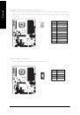
Страница 23 из 89 Please connect the power LED, PC peaker, reset switch and power switch etc of your chassis front panel to the F_PANEL connector according to the pin assignment below. 20 19 SPEAKSpeaker Connector SPEAK+ Power Switch Message LED/ Power/ Sleep LED PW+ NC RES+ RESHDHD+ PW- MSGMSG+ HD (IDE Hard Disk
Страница 24 из 89 English 13) AZALIA_FP (Front Audio Panel Connector) Please make sure the pin assigment on the cable is the same as the pin assigment on the motherboard header. To find out if the chassis you are buying support front audio panel connector, please contact your dealer. 10 9 Pin No. 1 Definition MIC2_L
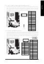
Страница 25 из 89 Be careful with the polarity of the front USB connector. Check the pin assignment carefully while you connect the front USB cable, incorrect connection between the cable and connector will make the device unable to work or even damage it. For optional front USB cable, please contact your local
Страница 26 из 89 English 17) IR Be careful with the polarity of the IR connector while you connect the IR. Please contact your nearest dealer for optional IR device. Pin No. Definition 1 2 VCC No Pin 3 4 IR RX GND 5 1 IR TX 18) COMA (Serial Port Connector) Be careful with the polarity of the COMA connector. Check
Страница 27 из 89 You may clear the CMOS data to its default values by this jumper. To clear CMOS, temporarily short 1-2 pin. Default doesn't include the "Shunter" to prevent from improper use this jumper. Open: Normal 1 Short: Clear CMOS 1 20) BAT(Battery) Danger of explosion if battery is incorrectly replaced.
Страница 29 из 89 BIOS (Basic Input and Output System) includes a CMOS SETUP utility which allows user to configure required settings or to activate certain system features. The CMOS SETUP saves the configuration in the CMOS SRAM of the motherboard. When the power is turned off, the battery on the motherboard
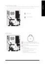
Страница 30 из 89 English The Main Menu (For example: BIOS Ver. : F1) Once you enter Award BIOS CMOS Setup Utility, the Main Menu (as figure below) will appear on the screen. Use arrow keys to select among the items and press <Enter> to accept or enter the sub-menu. CMOS Setup Utility-Copyright (C) 1984-2004 Award
Страница 31 из 89 Optimized Defaults indicates the value of the system parameters which the system would be in best performance configuration. Set Supervisor Password Change, set, or disable password. It allows you to limit access to the system and Setup, or just to Setup. Set User Password Change, set, or disable
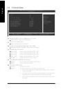
Страница 32 из 89 English 2-1 Standard CMOS Features CMOS Setup Utility-Copyright (C) 1984-2004 Award Software Standard CMOS Features Date (mm:dd:yy) Time (hh:mm:ss) Fri, May 21 2004 22:31:24 Item Help Menu Level IDE Channel 0 Master IDE Channel 0 Slave [None] [None] Change the day, month, year Drive A Drive B
Страница 33 из 89 The category identifies the types of floppy disk drive A or drive B that has been installed in the computer. None No floppy drive installed 360K, 5.25" 5.25 inch PC-type standard drive; 360K byte capacity. 1.2M, 5.25" 5.25 inch AT-type high-density drive; 1.2M byte capacity (3.5 inch when 3 Mode is
Страница 34 из 89 English 2-2 Advanced BIOS Features CMOS Setup Utility-Copyright (C) 1984-2004 Award Software Advanced BIOS Features Hard Disk Boot Priority First Boot Device Second Boot Device Third Boot Device Password Check # CPU Hyper-Threading Limit CPUID Max. to 3 On-Chip Frame Buffer Size : Move Enter:
Страница 35 из 89 Enabled Disabled Enables CPU Hyper Threading Feature. Please note that this feature is only working for operating system with multi processors mode supported. (Default value) Disables CPU Hyper Threading. Limit CPUID Max. to 3 Enabled Disabled Limit CPUID Maximum value to 3 when use older OS like
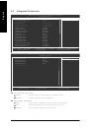
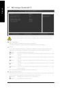
Страница 36 из 89 English 2-3 Integrated Peripherals CMOS Setup Utility-Copyright (C) 1984-2004 Award Software Integrated Peripherals On-Chip Primary PCI IDE On-Chip RAID/AHCI Mode x On-Chip SATA Mode x PATA IDE Set to SATA Port 0/2 Set to SATA Port 1/3 Set to USB Controller USB 2.0 Controller USB Keyboard Support
Страница 37 из 89 Disabled Auto Combined Enhanced Non-Combined Disable this function. BIOS will auto detect. (Default value) Set On-Chip SATA mode to Combined, you can use up to 4 HDDs on the motherboard; 2 for SATA and the other for PATA IDE. Set On-Chip SATA mode to Enhanced, the motherboard allows up to 6 HDDs to
Страница 38 из 89 English Onboard H/W LAN (LAN1 port) Enabled Disabled Enable onboard H/W LAN function. (Default value) Disable this function. Onboard H/W LAN2 (LAN2 port) Enabled Disabled Enable onboard H/W LAN2 function. (Default value) Disable this function. Onboard LAN1 Boot ROM (LAN1 port) This function decide
Страница 39 из 89 SPP EPP ECP ECP+EPP English Parallel Port Mode Using Parallel port as Standard Parallel Port. (Default value) Using Parallel port as Enhanced Parallel Port. Using Parallel port as Extended Capabilities Port. Using Parallel port as ECP & EPP mode. ECP Mode Use DMA 3 1 2-4 Set ECP Mode Use DMA to 3.
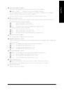
Страница 40 из 89 English Resume by Alarm You can set "Resume by Alarm" item to enabled and key in Data/time to power on system. Disabled Disable this function. (Default value) Enabled Enable alarm function to POWER ON system. If RTC Alarm Lead To Power On is Enabled. Date (of Month) Alarm : Everyday, 1~31 Time (hh:
Страница 41 из 89 PnP/PCI Configurations CMOS Setup Utility-Copyright (C) 1984-2004 Award Software PnP/PCI Configurations PCI 1 IRQ Assignment PCI 2 IRQ Assignment [Auto] [Auto] Item Help Menu Level Device(s) using this INT: Display Cntrlr - Bus 0 Dev 2 Func 0 Multimedia Device - Bus 0 Dev 27 Func 0 Bridge Device -
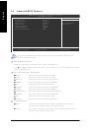
Страница 42 из 89 English 2-6 PC Health Status CMOS Setup Utility-Copyright (C) 1984-2004 Award Software PC Health Status Vcore DDR18V +3.3V +12V Current CPU Temperature Current CPU FAN Speed Current POWER FAN Speed Current SYSTEM FAN Speed CPU Warning Temperature CPU FAN Fail Warning POWER FAN Fail Warning SYSTEM
Страница 43 из 89 In order to make "CPU Smart FAN Control" function work properly, please set the pin number according to the CPU FAN that you used. 3 PIN Set CPU FAN Type to 3 pins. (Default value) 4 PIN Set CPU FAN Type to 4 pins. - 43 - BIOS Setup English CPU FAN PIN Type
Страница 44 из 89 English 2-7 MB Intelligent Tweaker(M.I.T.) CMOS Setup Utility-Copyright (C) 1984-2004 Award Software MB Intelligent Tweaker(M.I.T.) CPU Clock Ratio C.I.A.2 CPU Host Clock Control x CPU Host Frequency (Mhz) Memory Frequency For Memory Frequency (Mhz) DIMM OverVoltage Control PCI-E OverVolatge
Страница 45 из 89 This item will be available when "CPU Host Clock Control" is set to Enabled. 100MHz ~ 355MHz Set CPU Host Clock from 100MHz to 355MHz. If you use FSB533 Pentium 4 processor, please set "CPU Clock" to 133MHz.If you use FSB800 Pentium 4 processor, please set "CPU Clock" to 200MHz. Incorrect using it
Страница 46 из 89 English 2-8 Load Fail-Safe Defaults CMOS Setup Utility-Copyright (C) 1984-2004 Award Software Standard CMOS Features Load Fail-Safe Defaults Advanced BIOS Features Load Optimized Defaults Integrated Peripherals Set Supervisor Password Power Management Setup Set User Password Load Fail-Safe
Страница 47 из 89 English 2-10 Set Supervisor/User Password CMOS Setup Utility-Copyright (C) 1984-2004 Award Software Standard CMOS Features Advanced BIOS Features Integrated Peripherals Power Management Setup PnP/PCI Configurations Enter Password: PC Health Status MB Intelligent Tweaker(M.I.T.) Load Fail-Safe
Страница 48 из 89 English 2-11 Save & Exit Setup CMOS Setup Utility-Copyright (C) 1984-2004 Award Software Standard CMOS Features Load Fail-Safe Defaults Advanced BIOS Features Load Optimized Defaults Integrated Peripherals Set Supervisor Password Power Management Setup Set User Password PnP/PCI Configurations Save
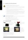
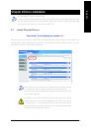
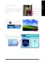
Страница 49 из 89 Pictures below are shown in Windows XP. Insert the driver CD-title that came with your motherboard into your CD-ROM drive, the driver CD-title will auto start and show the installation guide. If not, please double click the CD-ROM device icon in "My computer", and execute the Run.exe. 3-1 Install
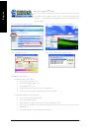
Страница 50 из 89 English 3-2 Software Applications This page displays all the tools that Gigabyte developed and some free software, you can choose anyone you want and press "install" to install them. 3-3 Driver CD Information This page lists the contents of software and drivers in this CD-title. GA-8GNXP-D
Страница 51 из 89 Hardware Information English 3-4 This page lists all device you have for this motherboard. 3-5 Contact Us Please see the last page for details. - 51 - Drivers Installation
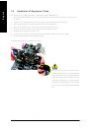
Страница 53 из 89 4-1 English Chapter 4 Appendix Unique Software Utilities (Not all model support these Unique Software Utilities, please check your MB features.) U-PLUS D.P.S. (Universal Plus Dual Power System) The U-Plus Dual Power System (U-Plus DPS) is a revolutionary eight-phase power circuit built for ultimate
Страница 54 из 89 English 4-1-1 Xpress Recovery Introduction What is Xpress Recovery ? Xpress Recovery is a utility used to back up and restore an OS partition. If the hard drive is not working properly, the user can restore the drive to its original state. 1. 2. 3. 4. 5. 6. Supports FAT16, FAT32, and NTFS formats
Страница 55 из 89 Press F9 during powering on the computer. (Text Mode) Press F9 during powering on the computer . English 2. Award Modular BIOS v6.00PG, An Energy Star Al ly Copyright (C) 1984-2004, Award Software, Inc. Intel 865PE AGPSet BIOS for 8IPE1000MT F1 Check System Health OK . . . F9 For Xpress Recovery
Страница 56 из 89 English 1. Execute Backup Utility: Press B to Backup your System or Esc to Exit The backup utility will automatically scan your system and back up data as a backup image in your hard drive. Not all systems support access to Xpress Recovery by pressing the F9 key during computer power on. If this is
Страница 57 из 89 A. What is Dual BIOS Technology? Dual BIOS means that there are two system BIOS (ROM) on the motherboard, one is the Main BIOS and the other is Backup BIOS. Under the normal circumstances, the system works on the Main BIOS. If the Main BIOS is corrupted or damaged, the Backup BIOS can take over
Страница 58 из 89 English c. Dual BIOS Item explanation: Wide Range Protection: Disable(Default), Enable Status 1: If any failure (ex. Update ESCD failure, checksum error or reset? occurs in the Main BIOS, just before the Operating System is loaded and after the power is on, and that the Wide Range Protection is set
Страница 59 из 89 Q-Flash TM is a BIOS flash utility embedded in Flash ROM. With this utility, users only have to stay in the BIOS menu when they want to update BIOS. Q-Flash?allows users to flash BIOS without any utility in DOS or Windows. Using Q-FlashTM indicating no more fooling around with any complicated
Страница 60 из 89 English Entering the Q-Flash TM utility: Step1: To use Q-Flash utility, you must press Del in the boot screen to enter BIOS menu. CMOS Setup Utility-Copyright (C) 1984-2004 Award Software Standard CMOS Features Advanced BIOS Features Integrated Peripherals Power Management Setup PnP/PCI
Страница 61 из 89 This section tells you how to update BIOS using the Q-Flash utility. As described in the "Before you begin" section above, you must prepare a floppy disk having the BIOS file for your motherboard and insert it to your computer. If you have already put the floppy disk into your system and have
Страница 62 из 89 English 3. Press Y button on your keyboard after you are sure to update BIOS. Then it will begin to update BIOS. The progress of updating BIOS will be displayed. Please do not take out the floppy disk when it begins flashing BIOS. 4. Press any keys to return to the Q-Flash menu when the BIOS
Страница 63 из 89 Press Del to enter BIOS menu after system reboots. When you are in BIOS menu, move to Load Fail-Safe Defaults item and press Enter to load BIOS Fail-Safe Defaults. Normally the system redetects all devices after BIOS has been upgraded. Therefore, we highly recommend reloading the BIOS defaults
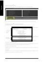
Страница 64 из 89 English Exploring the Q-FlashTM utility screen The Q-FlashBIOS utility screen consists of the following key components. Q-FlashTM utility bar Q-Flash Utility V1.30 Flash Type/Size.................................SST 49LF003A Task menu for Q-FlashTM utility Enter : Run Keep DMI Data Enable Update
Страница 65 из 89 Press Y button on your keyboard after you are sure to update BIOS. Then it will begin to update BIOS. The progress of updating BIOS will be shown at the same time. Q-Flash Utility V1.30 Flash Type/Size.................................SST 49LF003A 256K Keep DMI Data BIOS Now Updating Enable Update
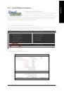
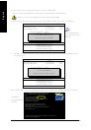
Страница 66 из 89 English Method 2 : @BIOSTM Utility If you do not have a DOS startup disk, we recommend that you use the new @BIOS utility. @BIOS allows users to update their BIOS under Windows. Just select the desired @BIOS server to download the latest version of BIOS. Fig 1. Installing the @BIOS utility Fig 2.
Страница 67 из 89 IV. Check out supported motherboard and Flash ROM: In the very beginning, there is "About this program" icon shown in dialog box. It can help you check out which kind of motherboard and which brand of Flash ROM are supported. 2. Note: I. In method I, if it shows two or more motherboard's model
Страница 68 из 89 English 4-1-3 Serial ATA BIOS Setting Utility Introduction RAID Levels RAID (Redundant Array of Independent Disks) is a method of combining two hard disk drives into one logical unit. The advantage of an Array is to provide better performance or data fault tolerance. Fault tolerance is achieved
Страница 69 из 89 Configuring the Intel RAID BIOS The Intel RAID BIOS setup lets you choose the RAID array type and which hard drives you want to make part of the array. Entering the RAID BIOS Setup 1. After rebooting your computer, wait until you see the RAID software prompting you to press Ctrl + I. The RAID
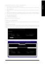
Страница 70 из 89 English Create RAID Volume Press Enter under Create RAID Volume to set up RAID. Intel(R) Application Accelerator RAID Option ROM v4.0.6180 Copyright(C) 2003-04 Intel Corporation. All Rights Reversed. [ CREATE VOLUME MENU ] Name : RAID_Volume0 RAID Level : RAID0(Stripe) Disks : Select Disks Strip
Страница 71 из 89 Intel(R) Application Accelerator RAID Option ROM v4.0.6180 Copyright(C) 2003-04 Intel Corporation. All Rights Reversed. [ CREATE VOLUME MENU ] Name : RAID_Volume0 RAID Level : RAID0(Stripe) Disks : Select Disks Strip Size : 128KB Capacity : 223.5 GB Create Volume [ HELP ] Choose the RAID level best
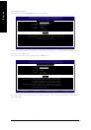
Страница 72 из 89 English Press Enter under the Create Volume item. Intel(R) Application Accelerator RAID Option ROM v4.0.6180 Copyright(C) 2003-04 Intel Corporation. All Rights Reversed. [ CREATE VOLUME MENU ] Name : RAID_Volume0 RAID Level : RAID0(Stripe) Disks : Select Disks Strip Size : 128KB Capacity : 223.5 GB
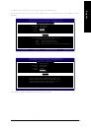
Страница 73 из 89 Intel(R) Application Accelerator RAID Option ROM v4.0.6180 Copyright(C) 2003-04 Intel Corporation. All Rights Reversed. [ MAIN MENU ] 1. Create RAID Volume 2. Delete RAID Volume 3. Reset Disks to Non-RAID 4. Exit [ DISK/VOLUME INFORMATION ] RAID Volumes : ID Name 0 RAID_Volume0 Level RAID(Stripe)
Страница 74 из 89 English Installing the RAID drivers For the Windows operating system (Win NT, WinXP, Win2000 ), for IDE RAID/SCSI/Serial ATA functioning, the driver must first be transferred to a floppy disk. Please follow the steps below to complete driver transfer to a floppy disk: 1) Please insert the provided
Страница 75 из 89 2- / 4- / 6- / 8- Channel Audio Function Introduction This motherboard provide 6 audio connector. You are able to use 2-/ 4-/6-/8-channnels audio feature by audio software selection. Introduction of audio connectors: You may connect CD-ROM/DVD-ROM, walkman or others audio input to Line In. The
Страница 76 из 89 English STEP 3: Click "Speaker Configuration" then click on the left selection bar and select "2CH Speaker" to complete 2 channel audio configuration. 4 Channel Audio Setup STEP 1 : Connect the front channels to "Front Speaker Out", the rear channels to "Rear Speaker Out". Front Speaker Out Rear
Страница 77 из 89 STEP 1 : Connect the front channels to "Front Speaker Out", the rear channels to "Rear Speaker Out", and the Center/Subwoofer channels to "Center/Subwoofer Speaker Out". Front Speaker Out Rear Speaker Out Center/Subwoofer Speaker Out STEP 2 : Following installation of the audio driver, you find a
Страница 78 из 89 English 8 Channel Audio Setup STEP 1 : Connect the front channels to "Front Speaker Out", the rear channels to "Rear Speaker Out", the Center/ Subwoofer channels to "Center/Subwoofer Speaker Out", and the side channels to "Side Speaker Out". Front Speaker Out Rear Speaker Out Center/Subwoofer
Страница 79 из 89 English Jack-Sensing Introduction Jack-Sensing provides audio connectors error-detection function. Install Microsoft DirectX8.1 or later version before to enable Jack-Sensing support for Windows 98/ 98SE/ 2000/ ME. After you install an audio device, a screen of a list would pop up from the audio
Страница 80 из 89 English 4-2 Troubleshooting Below is a collection of general asked questions. To check general asked questions based on a specific motherboard model, please log on to http://tw.giga-byte.com/faq/faq.htm Question 1: I cannot see some options that were included in previous BIOS after updating BIOS.
Страница 81 из 89 Question 10: Sometimes I hear different continuous beeps from computer after system boots up. What do these beeps usually stand for? Answer: The beep codes below may help you identify the possible computer problems. However, they are only for reference purposes. The situations might differ from