Страница 9 из 81 1-1 English Chapter 1 Hardware Installation Considerations Prior to Installation Preparing Your Computer The motherboard contains numerous delicate electronic circuits and components which can become damaged as a result of electrostatic discharge (ESD). Thus, prior to installation, please follow
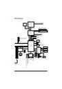
Страница 10 из 81 English 1-2 Feature Summary CPU Chipset Memory Slots IDE Connections FDD Connections Onboard SATA Peripherals Onboard LAN Onboard Audio I/O Control Hardware Monitor Supports the latest Intel ® Pentium® 4 LGA775 CPU Supports 800/533MHz FSB L2 cache varies with CPU Northbridge: Intel® 915GL Express
Страница 11 из 81 Additional Features Overclocking Form Factor Use of licensed AWARD BIOS Supports Q-Flash Supports @BIOS Supports EasyTune 5 (only supports Hardware Monitor function) Over Clock via BIOS (DDR) Micro ATX form factor; 24.4 cm x 24.4 cm - 11 - Hardware Installation English BIOS
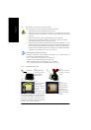
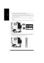
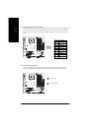
Страница 12 из 81 English 1-3 Installation of the CPU and Heatsink Before installing the CPU, please comply with the following conditions: 1. Please make sure that the motherboard supports the CPU. 2. Please take note of the one indented corner of the CPU. If you install the CPU in the wrong direction, the CPU will
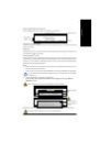
Страница 13 из 81 Male Push Pin The top of Female Push Pin Female Push Pin Fig.1 Please apply an even layer of heatsink paste on the surface of the installed CPU. Fig. 2 (Turning the push pin along the direction of arrow is to remove the heatsink, on the contrary, is to install.)Please note the direction of arrow
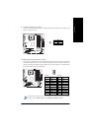
Страница 14 из 81 English 1-4 Installation of Memory Before installing the memory modules, please comply with the following conditions: 1. Please make sure that the memory used is supported by the motherboard. It is recommended that memory of similar capacity, specifications and brand be used. 2. Before installing
Страница 15 из 81 We'll strongly recommend our user to slot two DDR memory modules into the DIMMs with the same color in order for Dual Channel Technology to work. The following table is for Dual Channel Technology combination: (DS: Double Side, SS: Single Side) 2 memory modules 4 memory modules DDR 1 DS/SS X DS/SS
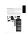
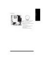
Страница 16 из 81 English 1-5 Install expansion cards You can install your expansion card by following the steps outlined below: 1. Read the related expansion card's instruction document before install the expansion card into the computer. 2. Remove your computer's chassis cover, screws and slot bracket from the
Страница 17 из 81 I/O Back Panel Introduction English 1-6 PS/2 Keyboard and PS/2 Mouse Connector To install a PS/2 port keyboard and mouse, plug the mouse to the upper port (green) and the keyboard o the lower port (purple). Parallel Port The parallel port allows connection of a printer, scanner and other peripheral
Страница 18 из 81 English Connect the rear surround speakers to this connector. Center/Subwoofer Speaker Out Connect the Center/Subwoofer speakers to this connector. Side Speaker Out Connect the side surround speakers to this connector. You can use audio software to configure 2-/4-/6-/8-channel audio functioning.
Страница 19 из 81 With the use of the power connector, the power supply can supply enough stable power to all the components on the motherboard. Before connecting the power connector, please make sure that all components and devices are properly installed. Align the power connector with its proper location on the
Страница 20 из 81 English 3/4) CPU_FAN / SYS_FAN (Cooler Fan Power Connector) The cooler fan power connector supplies a +12V power voltage via a 3-pin/4-pin (only for CPU_FAN) power connector and possesses a foolproof connection design. Most coolers are designed with color-coded power connector wires. A red power
Страница 21 из 81 An IDE device connects to the computer via an IDE connector. One IDE connector can connect to one IDE cable, and the single IDE cable can then connect to two IDE devices (hard drive or optical drive). If you wish to connect two IDE devices, please set the jumper on one IDE device as Master and the
Страница 22 из 81 English 8) F_PANEL (Front Panel Jumper) Please connect the power LED, PC peaker, reset switch and power switch etc of your chassis front panel to the F_PANEL connector according to the pin assignment below. Power Switch Message LED/ Power/ Sleep LED SPEAK- SPEAK+ PW- MSGMSG+ PW+ 2 1 Speaker
Страница 23 из 81 This 2-pin connector allows your system to enable or disable the "Case Open" item in BIOS, if the system case begin remove. Pin No. Definition 1 Signal 2 GND 1 10) AZALIA_FP(Front Audio Panel Connector) This connector is supported to connect HD(High Definition) Audio and AC'97 Audio. Check the pin
Страница 24 из 81 English 11) CD_IN (CD IN) Connect CD-ROM or DVD-ROM audio out to the connector. Pin No. 1 2 3 4 1 Definition CD-L GND GND CD -R 12) F_ USB1 / F_USB2 (Front USB Connector) Be careful with the polarity of the front USB connector. Check the pin assignment carefully while you connect the front USB
Страница 25 из 81 Serial interface standard set by Institute of Electrical and Electronics Engineers, which has features like high speed, high bandwidth and hot plug. Be careful with the polarity of the IEEE1394 connector. Check the pin assignment carefully while you connect the IEEE1394 cable, incorrect connection
Страница 26 из 81 English 15) COMA/COMB (Serial Port Connector) Be careful with the polarity of the COM connector. Check the pin assignment carefully while you connect the COM cable, incorrect connection between the cable and connector will make the device unable to work or even damage it. For optional COM cable,
Страница 27 из 81 English 17) BAT(Battery) Danger of explosion if battery is incorrectly replaced. Replace only with the same or equivalent type recommended by the manufacturer. Dispose of used batteries according to the manufacturer's instructions. If you want to erase CMOS... 1.Turn OFF the computer and unplug the
Страница 29 из 81 BIOS (Basic Input and Output System) includes a CMOS SETUP utility which allows user to configure required settings or to activate certain system features. The CMOS SETUP saves the configuration in the CMOS SRAM of the motherboard. When the power is turned off, the battery on the motherboard
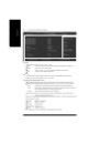
Страница 30 из 81 English The Main Menu (For example: BIOS Ver. : E3) Once you enter Award BIOS CMOS Setup Utility, the Main Menu (as figure below) will appear on the screen. Use arrow keys to select among the items and press <Enter> to accept or enter the sub-menu. CMOS Setup Utility-Copyright (C) 1984-2005 Award
Страница 31 из 81 English Set User Password Change, set, or disable password. It allows you to limit access to the system. Save & Exit Setup Save CMOS value settings to CMOS and exit setup. Exit Without Saving Abandon all CMOS value changes and exit setup. - 31 - BIOS Setup
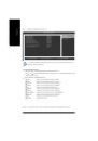
Страница 32 из 81 English 2-1 Standard CMOS Features CMOS Setup Utility-Copyright (C) 1984-2005 Award Software Standard CMOS Features Date (mm:dd:yy) Time (hh:mm:ss) Thu, Apr 29 2004 22:31:24 Item Help Menu Level IDE Channel 0 Master IDE Channel 0 Slave IDE Channel 2 Master IDE Channel 2 Slave IDE Channel 3 Master
Страница 33 из 81 The category identifies the types of floppy disk drive A or drive B that has been installed in the computer. None No floppy drive installed 360K, 5.25" 5.25 inch PC-type standard drive; 360K byte capacity. 1.2M, 5.25" 5.25 inch AT-type high-density drive; 1.2M byte capacity (3.5 inch when 3 Mode is
Страница 34 из 81 English 2-2 Advanced BIOS Features CMOS Setup Utility-Copyright (C) 1984-2005 Award Software Advanced BIOS Features Hard Disk Boot Priority First Boot Device Second Boot Device Third Boot Device Password Check # CPU Hyper-Threading Limit CPUID Max. to 3 No-Execute Memory Protect (Note) CPU Enhanced
Страница 35 из 81 Setup System The system will boot but will not access to Setup page if the correct password is not entered at the prompt. (Default value) The system will not boot and will not access to Setup page if the correct password is not entered at the prompt. CPU Hyper-Threading Enabled Disabled Enables CPU
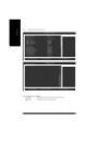
Страница 36 из 81 English 2-3 Integrated Peripherals CMOS Setup Utility-Copyright (C) 1984-2005 Award Software Integrated Peripherals On-Chip Primary PCI IDE On-Chip SATA Mode x PATA IDE Set to SATA Port 0/2 Set to SATA Port 1/3 Set to USB Controller USB 2.0 Controller USB Keyboard Support USB Mouse Support Azalia
Страница 37 из 81 Disabled Auto Combined Enhanced Non-Combined Disable this function. BIOS will auto detect. (Default value) Set On-Chip SATA mode to Combined, you can use up to 4 HDDs on the motherboard; 2 for SATA and the other for PATA IDE. Set On-Chip SATA mode to Enhanced, the motherboard allows up to 6 HDDs to
Страница 38 из 81 English Onboard H/W 1394 Enabled Disabled Enable onboard IEEE 1394 function.(Default value) Disable this function. Onboard H/W LAN Enabled Disabled Enable Onboard H/W LAN function. (Default value) Disable this function. Onboard LAN Boot ROM This function decide whether to invoke the boot ROM of the
Страница 39 из 81 SPP EPP ECP ECP+EPP English Parallel Port Mode Using Parallel port as Standard Parallel Port. (Default value) Using Parallel port as Enhanced Parallel Port. Using Parallel port as Extended Capabilities Port. Using Parallel port as ECP & EPP mode. ECP Mode Use DMA 3 1 2-4 Set ECP Mode Use DMA to 3.
Страница 40 из 81 English Resume by Alarm You can set "Resume by Alarm" item to enabled and key in Date/time to power on system. Disabled Disable this function. (Default value) Enabled Enable alarm function to POWER ON system. If RTC Alarm Lead To Power On is Enabled. Date (of Month) Alarm : Everyday, 1~31 Time (hh:
Страница 41 из 81 PnP/PCI Configurations CMOS Setup Utility-Copyright (C) 1984-2005 Award Software PnP/PCI Configurations PCI 1 IRQ Assignment PCI 2 IRQ Assignment [Auto] [Auto] : Move Enter: Select F5: Previous Values +/-/PU/PD: Value F6: Fail-Safe Default Item Help Menu Level F10: Save ESC: Exit F1: General Help
Страница 42 из 81 English Reset Case Open Status Case Opened If the case is closed, "Case Opened" will show "No". If the case have been opened, "Case Opened" will show "Yes". If you want to reset "Case Opened" value, set "Reset Case Open Status" to "Enabled" and save CMOS, your computer will restart. Current
Страница 43 из 81 MB Intelligent Tweaker(M.I.T.) CMOS Setup Utility-Copyright (C) 1984-2005 Award Software MB Intelligent Tweaker(M.I.T.) CPU Clock Ratio Memory Frequency For Memory Frequency (Mhz) : Move Enter: Select F5: Previous Values [15X] [Auto] 400 +/-/PU/PD: Value F6: Fail-Safe Default Item Help Menu Level
Страница 44 из 81 English 2-8 Load Fail-Safe Defaults CMOS Setup Utility-Copyright (C) 1984-2005 Award Software Standard CMOS Features Load Fail-Safe Defaults Advanced BIOS Features Load Optimized Defaults Integrated Peripherals Set Supervisor Password Power Management Setup Set User Password Load Fail-Safe Defaults
Страница 45 из 81 English 2-10 Set Supervisor/User Password CMOS Setup Utility-Copyright (C) 1984-2005 Award Software Standard CMOS Features Advanced BIOS Features Integrated Peripherals Power Management Setup PnP/PCI Configurations Enter Password: PC Health Status MB Intelligent Tweaker(M.I.T.) Load Fail-Safe
Страница 46 из 81 English 2-11 Save & Exit Setup CMOS Setup Utility-Copyright (C) 1984-2005 Award Software Standard CMOS Features Load Fail-Safe Defaults Advanced BIOS Features Load Optimized Defaults Integrated Peripherals Set Supervisor Password Power Management Setup Set User Password PnP/PCI Configurations Save
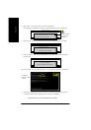
Страница 47 из 81 Pictures below are shown in Windows XP. Insert the driver CD-title that came with your motherboard into your CD-ROM drive, the driver CD-title will auto start and show the installation guide. If not, please double click the CD-ROM device icon in "My computer", and execute the Run.exe. 3-1 Install
Страница 48 из 81 English 3-2 Software Applications This page displays all the tools that Gigabyte developed and some free software, you can choose anyone you want and press "install" to install them. 3-3 Driver CD Information This page lists the contents of software and drivers in this CD-title. GA-8I915GL-MF
Страница 49 из 81 Hardware Information English 3-4 This page lists all device you have for this motherboard. 3-5 Contact Us Please see the last page for details. - 49 - Install Drivers
Страница 51 из 81 4-1 English Chapter 4 Appendix Unique Software Utilities (Not all model support these Unique Software Utilities, please check your MB features.) U-PLUS D.P.S. (Universal Plus Dual Power System) The U-Plus Dual Power System (U-Plus DPS) is a revolutionary eight-phase power circuit built for ultimate
Страница 52 из 81 English 4-1-1 EasyTune 5 Introduction EasyTune 5 presents the most convenient Windows based system performance enhancement and manageability utility. Featuring several powerful yet easy to use tools such as 1) Overclocking for enhancing system performance, 2) C.I.A. and M.I.B. for special
Страница 53 из 81 What is Xpress Recovery ? Xpress Recovery is a utility used to back up and restore an OS partition. If the hard drive is not working properly, the user can restore the drive to its original state. 1. 2. 3. 4. 5. 6. Supports FAT16, FAT32, and NTFS formats Must be connected to the IDE1 Master Allows
Страница 54 из 81 English 2. Press F9 during powering on the computer. (Text Mode) Press F9 during powering on the computer . Award Modular BIOS v6.00PG, An Energy Star Ally Copyright (C) 1984-2004, Award Software, Inc. Intel 865PE AGPSet BIOS for 8IPE1000MT F1 Check System Health OK . . . F9 For Xpress Recovery
Страница 55 из 81 Press B to Backup your System or Esc to Exit The backup utility will automatically scan your system and back up data as a backup image in your hard drive. Not all systems support access to Xpress Recovery by pressing the F9 key during computer power on. If this is the case, please use the boot from
Страница 56 из 81 English 4-1-3 Flash BIOS Method Introduction Method 1 : Q-FlashTM Utility Q-Flash TM is a BIOS flash utility embedded in Flash ROM. With this utility, users only have to stay in the BIOS menu when they want to update BIOS. Q-Flash?allows users to flash BIOS without any utility in DOS or Windows.
Страница 57 из 81 English Entering the Q-FlashTM utility: Step1: To use Q-Flash utility, you must press Del in the boot screen to enter BIOS menu. CMOS Setup Utility-Copyright (C) 1984-2004 Award Software Standard CMOS Features Advanced BIOS Features Select Language Load Fail-Safe Defaults Integrated Peripherals
Страница 58 из 81 English Using the Q-FlashTM utility: This section tells you how to update BIOS using the Q-Flash utility. As described in the "Before you begin" section above, you must prepare a floppy disk having the BIOS file for your motherboard and insert it to your computer. If you have already put the floppy
Страница 59 из 81 English 3. Press Y button on your keyboard after you are sure to update BIOS. Then it will begin to update BIOS. The progress of updating BIOS will be displayed. Please do not take out the floppy disk when it begins flashing BIOS. 4. Press any keys to return to the Q-Flash menu when the BIOS
Страница 60 из 81 English 6. Press Del to enter BIOS menu after system reboots. When you are in BIOS menu, move to Load Fail-Safe Defaults item and press Enter to load BIOS Fail-Safe Defaults. Normally the system redetects all devices after BIOS has been upgraded. Therefore, we highly recommend reloading the BIOS
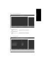
Страница 61 из 81 The Q-FlashBIOS utility screen consists of the following key components. Q-FlashTM utility bar Q-Flash Utility V1.30 Flash Type/Size.................................SST 49LF003A Task menu for Q-FlashTM utility Enter : Run Keep DMI Data Enable Update BIOS from Floppy Save BIOS to Floppy :Move
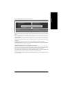
Страница 62 из 81 English 3. Press Y button on your keyboard after you are sure to update BIOS. Then it will begin to update BIOS. The progress of updating BIOS will be shown at the same time. Q-Flash Utility V1.30 Flash Type/Size.................................SST 49LF003A 256K Keep DMI Data BIOS Now Updating
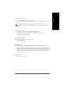
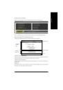
Страница 63 из 81 If you do not have a DOS startup disk, we recommend that you use the new @BIOS utility. @BIOS allows users to update their BIOS under Windows. Just select the desired @BIOS server to download the latest version of BIOS. Fig 1. Installing the @BIOS utility Fig 2. Installation Complete and Run @BIOS
Страница 64 из 81 English III. Save BIOS In the very beginning, there is "Save Current BIOS" icon shown in dialog box. It means to save the current BIOS version. IV. Check out supported motherboard and Flash ROM: In the very beginning, there is "About this program" icon shown in dialog box. It can help you check out
Страница 65 из 81 This motherboard provide 6 audio connector. You are able to use 2-/ 4-/6-/8-channnels audio feature by audio software selection. Introduction of audio connectors: You may connect CD-ROM/DVD-ROM, walkman or others audio input to Line In. The front channels or earphone can be connected to Line In
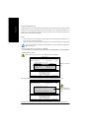
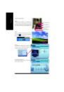
Страница 66 из 81 English STEP 3: Click "Speaker Configuration" then click on the left selection bar and select "2CH Speaker" to complete 2 channel audio configuration. 4 Channel Audio Setup STEP 1 : Connect the front channels to "Front Speaker Out", the rear channels to "Rear Speaker Out". Front Speaker Out Rear
Страница 67 из 81 STEP 1 : Connect the front channels to "Front Speaker Out", the rear channels to "Rear Speaker Out", and the Center/Subwoofer channels to "Center/Subwoofer Speaker Out". Front Speaker Out Rear Speaker Out Center/Subwoofer Speaker Out STEP 2 : Following installation of the audio driver, you find a
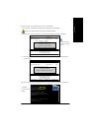
Страница 68 из 81 English 8 Channel Audio Setup STEP 1 : Connect the front channels to "Front Speaker Out", the rear channels to "Rear Speaker Out", the Center/ Subwoofer channels to "Center/Subwoofer Speaker Out", and the side channels to "Side Speaker Out". Front Speaker Out Rear Speaker Out Center/Subwoofer
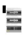
Страница 69 из 81 English Jack-Sensing Introduction Jack-Sensing provides audio connectors error-detection function. Install Microsoft DirectX8.1 or later version before to enable Jack-Sensing support for Windows 2000. After you install an audio device, a screen of a list would pop up from the audio software for you
Страница 70 из 81 English 4-2 Troubleshooting Below is a collection of general asked questions. To check general asked questions based on a specific motherboard model, please log on to http://tw.giga-byte.com/faq/faq.htm Question 1: I cannot see some options that were included in previous BIOS after updating BIOS.
Страница 71 из 81 Question 8: Sometimes I hear different continuous beeps from computer after system boots up. What do these beeps usually stand for? Answer: The beep codes below may help you identify the possible computer problems. However, they are only for reference purposes. The situations might differ from case
Страница 79 из 81 English Contact Us Taiwan (Headquarters) Japan GIGA-BYTE TECHNOLOGY CO., LTD. NIPPON GIGA-BYTE CORPORATION Address: No.6, Bau Chiang Road, Hsin-Tien, Taipei Hsien, WEB address : http://www.gigabyte.co.jp Taiwan TEL: +886 (2) 8912-4888 Singapore GIGA-BYTE SINGAPORE PTE. LTD. FAX: +886 (2) 8912-4003
Страница 80 из 81 English China Australia NINGBO G.B.T. TECH. TRADING CO., LTD. GIGABYTE TECHNOLOGY PTY. LTD. Tech. Support : http://cn.giga-byte.com/TechSupport/ServiceCenter.htm Tech. Support : http://www.giga-byte.com.au/TechSupport/ServiceCenter.htm Non-Tech. Support(Sales/Marketing) : Non-Tech.