AD8
USER'S MANUAL
INTRODUCTION:
Specification:
Operation:
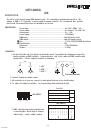
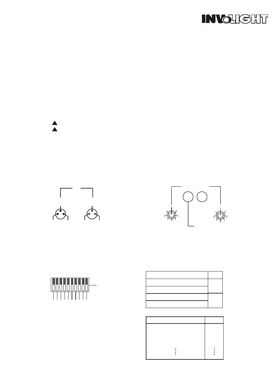
The unit is a four channel power DMX dimmer pack . It is controlled by analog input from 0v to 10v
voltage or DMX-512. It provide a power supply for analog controller. We recommend that you take
time to read this manual fully before you attempt to use the unit.
Power input........................................................................Ac 230v ~50Hz , 16A.
Power output......................................................................Per channel 5 A, total 16A.
Analog input ......................................................................0---10v.
Power supply.....................................................................15V,500mA
DMX input........................................................................3pin XLR male socket
DMX output......................................................................3pin XLR female socket.
Fuse ..................................................................................F 6.3A 250V,5X20MM. 4 purchase
Circuit breaker .................................................................16A.
Dimension.........................................................................318x165x96mm
Weight...............................................................................2.95kg
!
!
!
!
RISK OF ELECTRIC SHOCK
RISK OF ELECTRIC SHOCK
1. You must fixed the unit, then put the circuit breaker on off. According to the diagram to connect the
analog controller or DMX controller . Analog controller with 8 pin cable and DMX controller with
special cable . Put the output of controller to minimum.
2. Connect loading on output sockets .
3. All connection is ok ,you can connect to main power then turn on the circuit breaker .
4. To adjust the output of controller , the corresponding load from black to light.
5. DMX controller and analog controller can
be used together. which single is stronger,
which single control output loading.
CH1
NC
NC
CH1
CH4
CH2
CH3
CH3
CH2
CH4
NC
NC
IN
Through
Analog input: DC 0-10V
DC +15V 500mA
DC +15V 500mA
GND
GND
To analog controller
2
1
3
3
1
2
3
DMX OUT
DMX
DMX IN
FUNCTION
DMX ADDRESS
1: GND
2: DATA "
-
"
3: DATA " + "
1
1
1
0
1
0
1
1
any one of DIP switch 1-9 is on, DMX parallel
All of DIP switch 1-9 is off, auto parallel
any one of DIP switch 1-9 is on ,DMX
All of DIP switch 1-9 is off , Auto
2
2
0
1
1
0
0
1
3
3
0
0
0
1
1
1
4
4
0
0
0
0
0
1
5
5
0
0
0
0
0
1
6
6
0
0
0
0
0
1
7
7
0
0
0
0
0
1
8
8
0
0
0
0
0
1
9
9
0
0
0
0
0
1
511
10
Start address
1
2
3
4
5
1
0
1
2
5
6
2
4
8
1
6
3
2
6
4
1
2
8
Function
DMX ADDRESS
PY-S242028
1/2