Connecting the Units
<ENGLISH>
WARNING
• To avoid the risk of accident and the potential
violation of applicable laws, the front DVD or TV
(sold separately) feature should never be used
while the vehicle is being driven. Also, Rear
Displays should not be in a location where it is a
visible distraction to the driver.
• In some countries or states the viewing of images
on a display inside a vehicle even by persons other
than the driver may be illegal. Where such
regulations apply, they must be obeyed and this
unit’s DVD features should not be used.
CAUTION
• PIONEER does not recommend that you install or
service your display yourself. Installing or
servicing the product may expose you to risk of
electric shock or other hazards. Refer all
installation and servicing of your display to
authorized Pioneer service personnel.
• Secure all wiring with cable clamps or adhesive
tape. Do not allow any bare wiring to remain
exposed.
• Do not drill a hole into the engine compartment to
connect the yellow lead of the unit to the vehicle
battery. Engine vibration may eventually cause the
insulation to fail at the point where the wire passes
from the passenger compartment into the engine
compartment. Take extra care in securing the wire
at this point.
• It is extremely dangerous to allow the display lead
to become wound around the steering column or
gearshift. Be sure to install the display in such a
way that it will not obstruct driving.
• Make sure that wires will not interfere with
moving parts of the vehicle, such as the gearshift,
parking brake or seat sliding mechanism.
• Do not shorten any leads. If you do, the protection
circuit may fail to work properly.
Note:
•
This unit cannot be installed in a vehicle that
does not have an ACC (accessory) position on
the ignition switch.
•
Use this unit in other than the following
conditions could result in fire or malfunction.
— Vehicles with a 12-volt battery and negative
grounding.
— Speakers with 50 W (output value) and 4 ohm
to 8 ohm (impedance value).
•
To prevent short-circuit, overheating or
malfunction, be sure to follow the directions
below.
— Disconnect the negative terminal of the battery
before installation.
— Secure the wiring with cable clamps or adhe-
sive tape. To protect the wiring, wrap adhesive
tape around them where they lie against metal
parts.
— Place all cables away from moving parts, such
as gear shift and seat rails.
— Place all cables away from hot places, such as
near the heater outlet.
— Do not pass the yellow cable through a hole
into the engine compartment to connect to a
battery.
— Cover any disconnected cable connectors with
insulating tape.
— Do not shorten any cables.
— Never cut the insulation of the power cable of
this unit in order to share the power to other
equipment. Current capacity of the cable is
limited.
— Use a fuse of the rating prescribed.
— Never wire the speaker negative cable directly
to ground.
— Never band together multiple speaker’s nega-
tive cables.
•
Control signal is output through blue/white cable
when this unit is powered on. Connect it to an
external power amp’s system remote control or
the vehicle’s auto-antenna relay control terminal
(max. 300 mA, 12 V DC). If the vehicle is
equipped with a glass antenna, connect it to the
antenna booster power supply terminal.
•
Never connect blue/white cable to external power
amp’s power terminal. Also, never connect it to
the power terminal of the auto antenna.
Otherwise, battery drain or malfunction may
result.
•
Black cable is ground. This cable and other
product’s ground cable (especially, high-current
products such as power amp) must be wired
separately. Otherwise, fire or malfunction may
result if they are accidentally detached.
No ACC position
ACC position
O
N
S
T
A
R
T
O
F
F
A
C
C
O
N
S
T
A
R
T
O
F
F
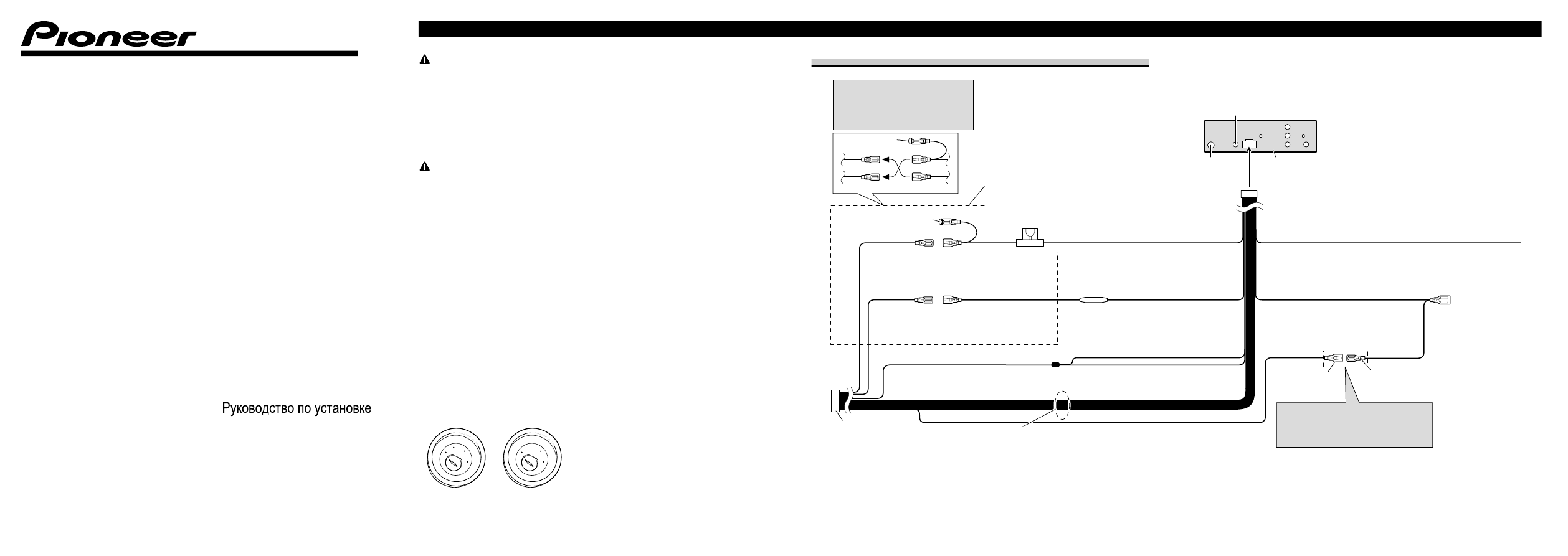
Power cable connection
1*
2*
4*
3*
5*
Note:
Depending on the kind of vehicle, the
function of 3* and 5* may be different. In
this case, be sure to connect 2* to 5* and 4*
to 3*.
Connect leads of the same
color to each other.
Cap (1*)
Do not remove cap if
this terminal is not in
use.
Yellow (3*)
Back-up (or
accessory)
Red (5*)
Accessory
(or back-up)
Yellow (2*)
Connect to the constant
12 V supply terminal.
Red (4*)
Connect to terminal controlled
by ignition switch (12 V DC).
ISO connector
Note:
In some vehicles, the ISO connector
may be divided into two. In this case,
be sure to connect to both connectors.
Speaker leads
White: Front
left
+
White/black: Front left
≠
Gray: Front
right
+
Gray/black: Front right
≠
Green: Rear
left
+
Green/black: Rear left
≠
Violet: Rear
right
+
Violet/black: Rear right
≠
Blue/white
Connect to system control terminal of the
power amp (max. 300 mA 12 V DC).
Blue/white (7*)
Connect to auto-antenna relay control
terminal (max. 300 mA 12 V DC).
The pin position of the ISO connector will differ
depends on the type of vehicle. Connect 6* and
7* when Pin 5 is an antenna control type. In
another type of vehicle, never connect 6* and 7*.
Yellow/black
If you use an equipment with Mute function, wire
this lead to the Audio Mute lead on that equipment.
If not, keep the Audio Mute lead free of any
connections.
Black (chassis ground)
Connect to a clean, paint-free metal location.
This product
Antenna jack
Fuse (10 A)
Fuse resistor
Wired remote input
Hard-wired remote control adaptor can be
connected (sold separately).
Blue/white (6*)
<KMIZX> <08I00000>
Printed
in
Thailand
<CRD4387-A/N> UW
Installation Manual
DVD RDS RECEIVER
DVD RDS êÖëàÇÖê
DVH-3100UB
ç‡Ô˜‡Ú‡ÌÓ ‚ í‡Ë·̉Â