2.2. Hydraulic connection
Note! Installation of safety valve included in the delivery set is necessary.
Do not install any stop valve between the safety valve and the inlet of the tank and do not block the drain hole of the
safety valve.
Demountable connectors should be used for the water heater connection to the water supply system.
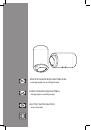
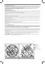
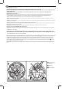
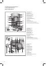
Standard connection (Fig. 1)
2.2.1. Safety valve supplied must be installed on the cold water inlet of the water heater (marked with the blue ring). It is
recommended to turn the safety valve no more than 3−4 turns, providing sealing with water-proof sealing material.
2.2.2.
2.2.3.
2.2.4.
safety valve of the water heater.
It will help to drain water from the water heater without safety valve removal.
2.2.5. To facilitate the access of air into the tank when draining water, it is recommended to install an additional T-piece with
2.2.6. When water pressure exceeds 5 bar, place before the safety valve a reducer to reduce the pressure.
2.2.7. Water is supplied to the water heater from the tank by gravity. For this purpose, the tank water outlet T-piece
supplying water to the heater and other places must be installed higher than the water heater top. Safety valve is not
necessary in this type of connection.
2.3. Electrical connection
manufacturer is not to be held responsible for any damage caused by the incorrect earthing of the system or for fault
defaults of the electricity supply.
2.3.1.
heater.
2.3.2. If the water heater is supplied without a power supply cable, use a cable featuring the same characteristics (type
H05VV-F 3x1,5 mm
2
, Ø 8,5 mm) for connection. The power supply cable should be threaded through the relevant hole on
corresponding screw.
2.3.3.
the symbol
. Fix the power supply cable using the cable clamps.
2.3.4. Make sure that the power supply voltage conforms to the water heater technical characteristics indicated on the data
plate.
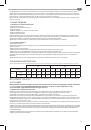
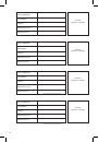
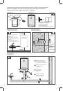
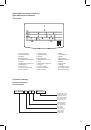
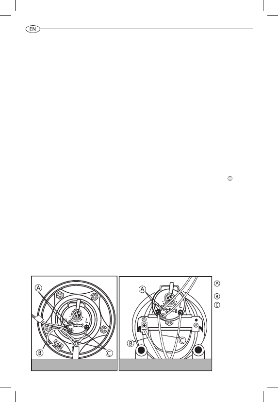
Flange on the 5 bolts
Autoclave flange
Indicating light
contacts
Earthing
Power supply
2.2. Hydraulic connection
Attention! Installation of safety valve Included In the delivery set Is necessary.
Do not Install any stop valve between the safety valve and the inlet of the tank and do not block the drain hole
of the safety valve.
Demountable connectors should be used for the water heater connection to the water supply system.
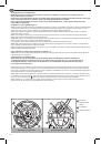
Standard connection (Fig. 1)
2.2.1.
Safety valve supplied must be installed on the cold water inlet of the water heater (marked with the blue ring). It is
recommended to turn the safety valve no more than 3-4 turns, providing sealing with water-proof sealing material.
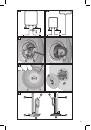
2.2.2.
Connect the inlet of the safety valve to the cold water line with a tube or flexible hose.
2.2.3.
Connect a tube or flexible hose to the hot water outlet of the water heater (marked with the red ring) for hot water
removal to the draw-off point.
2.2.4.
For easy maintenance, it is recommended to install a T-piece with shut-off valve between the cold water inlet and safety
valve of the water heater.
It will help to drain water from the water heater without safety valve removal.
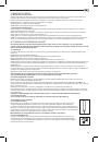
2.2.5.
To facilitate the access of air into the tank when draining water, it is recommended to install an additional T-piece with
shut-off valve at the hot water output.
2.2.6.
When water pressure exceeds 5 bar, place before the safety valve a reducer to reduce the pressure.
Connection to open tank filled with water (Fig. 2)
2.2.7.
Water is supplied to the water heater from the tank by gravity. Safety valve is not necessary in this type of connection.
2.3. Electrical connection
Attention! Electrical wiring should be done by a qualified technician, ensuring it complies with safety rules.
The manufacturer Is not to be held responsible for any damage caused by the Incorrect earthing of the system
or for fault defaults of the electricity supply.
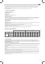
2.3.1.
If the water heater is supplied without a power supply cable, use a cable featuring the same characteristics (type H05VV-F
3x1,5 mm2, Ø 8,5 mm) for connection. The power supply cable should be threaded through the relevant hole on the cover of
the appliance and fixed to the thermostat terminals. Then every wire should be fixed in place by the corresponding screw.
2.3.2.
The water heater must be earthed. Grounding scheme should ensure the absence of electric potential on the body
of the water heater. The earth cable (of yellow-green color) should be fixed to the terminal marked by the symbol . Fix the
power supply cable using the cable clamps.
2.3.3.
Make sure that the power supply voltage conforms to the water heater technical characteristics indicated on the data
plate.
28