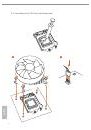
H81M-GL
23
English
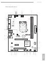
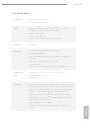
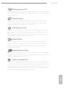
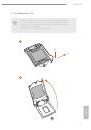
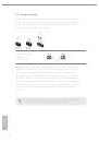
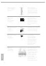
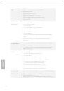
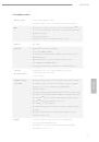
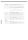
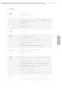
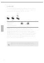
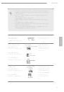
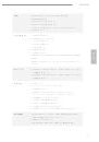
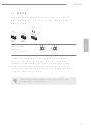
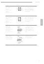
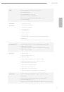
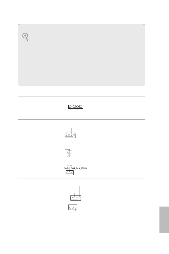
Chassis Speaker Header
(4-pin SPEAKER1)
(see p.1, No. 10)
Please connect the chassis
speaker to this header.
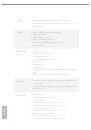
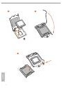
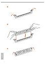
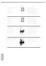
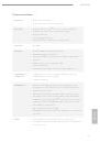
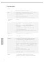
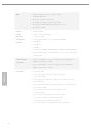
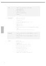
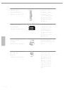
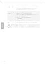
Chassis and Power Fan
Connectors
(4-pin CHA_FAN1)
(see p.1, No. 15)
(3-pin CHA_FAN2)
(see p.1, No. 21)
(3-pin PWR_FAN1)
(see p.1, No. 1)
Please connect fan cables
to the fan connectors and
match the black wire to
the ground pin.
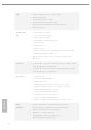
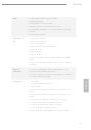
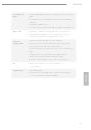
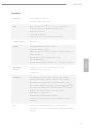
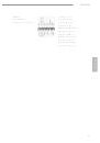
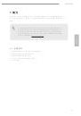
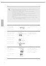
CPU Fan Connectors
(4-pin CPU_FAN1)
(see p.1, No. 3)
(3-pin CPU_FAN2)
(see p.1, No. 2)
This motherboard pro-
vides a 4-Pin CPU fan
(Quiet Fan) connector.
If you plan to connect a
3-Pin CPU fan, please
connect it to Pin 1-3.
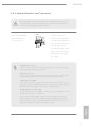
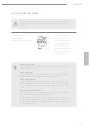
1. High Definition Audio supports Jack Sensing, but the panel wire on the chassis must
support HDA to function correctly. Please follow the instructions in our manual and
chassis manual to install your system.
2. If you use an AC’97 audio panel, please install it to the front panel audio header by
the steps below:
A. Connect Mic_IN (MIC) to MIC2_L.
B. Connect Audio_R (RIN) to OUT2_R and Audio_L (LIN) to OUT2_L.
C. Connect Ground (GND) to Ground (GND).
D. MIC_RET and OUT_RET are for the HD audio panel only. You don’t need to
connect them for the AC’97 audio panel.
E. To activate the front mic, go to the “FrontMic” Tab in the Realtek Control panel
and adjust “Recording Volume”.
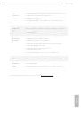
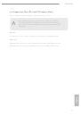
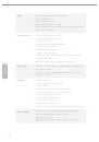
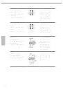
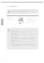
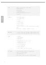
1
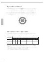
+5V
DUMMY
DUMMY
SPEAKER
GND
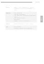
+12V
CHA_FAN_SPEED
FAN_SPEED_CONTROL
GND
+12V
FAN_SPEED
GND
+12V
CHA_FAN_SPEED
GND
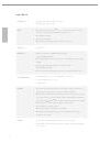
+12V
CPU_FAN_SPEED
FAN_SPEED_CONTROL