19
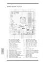
ASRock Z77 Pro4-M Motherboard
English
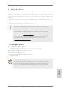
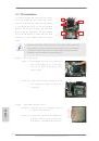
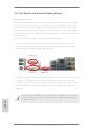
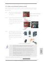
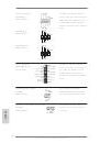
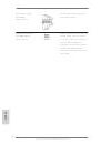
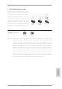
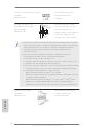
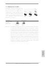
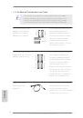
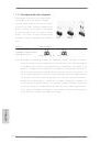
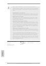
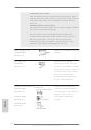
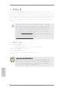
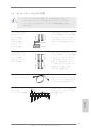
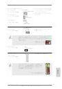
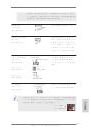
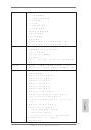
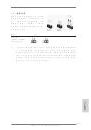
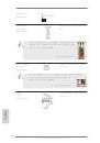
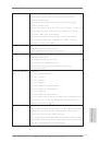
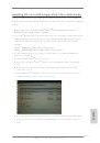
2.6 Expansion Slots (PCI Express Slots)
There are 4 PCI Express slots on this motherboard.
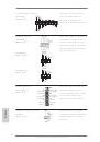
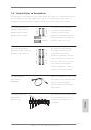
PCIE slots: PCIE1 (PCIE 3.0 x16 slot) is used for PCI Express x16 lane width
graphics cards, or to install PCI Express graphics cards to support
CrossFireX
TM
function.
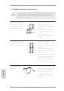
PCIE2 (PCIE 2.0 x1 slot) is used for a PCI Express x1 lane width card,
such as a Gigabit LAN card or SATA2 card, etc.
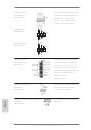
PCIE3 (PCIE 2.0 x16 slot) is used for PCI Express x1 lane width graph-
ics cards.
PCIE4 (PCIE 2.0 x16 slot) is used for PCI Express x4 lane width graph-
ics cards, or to install PCI Express graphics cards to support CrossFi-
reX
TM
function. And for installing ASRock Game Blaster.
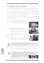
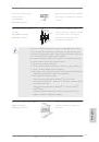
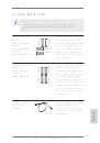
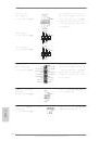
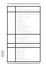
1. In single VGA card mode, it is recommended to install a PCI Express
x16 graphics card on PCIE1 slot.
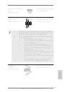
2. In CrossFireX
TM
mode, please install the PCI Express x16 graphics
cards on PCIE1 and PCIE4 slots. Therefore, PCIE1 will work at x16
bandwidth, while PCIE4 works at x4 bandwidth.
3. Please connect a chassis fan to the motherboard’s chassis fan
connector (CHA_FAN1 or CHA_FAN2) when using multiple
graphics cards for better thermal environment.
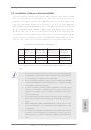
4. Only PCIE1 slot supports Gen 3 speed. To run the PCI Express in
Gen 3 speed, please install an Ivy Bridge CPU. If you install a Sandy
Bridge CPU, the PCI Express will run only at PCI Express Gen 2
speed.
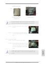
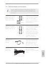
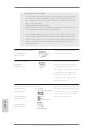
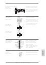
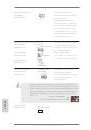
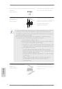
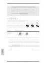
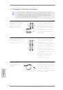
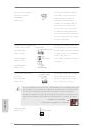
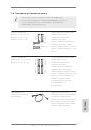
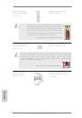
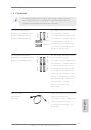
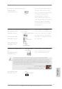
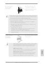
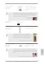
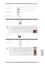
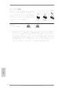
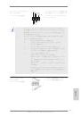
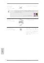
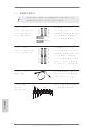
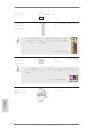
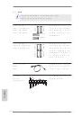
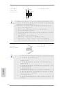
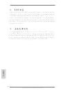
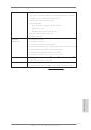
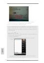
Installing an expansion card
Step 1.
Before installing an expansion card, please make sure that the power
supply is switched off or the power cord is unplugged. Please read the
documentation of the expansion card and make necessary hardware
settings for the card before you start the installation.
Step 2.
Remove the system unit cover (if your motherboard is already installed
in a chassis).
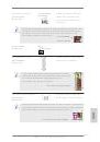
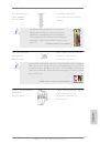
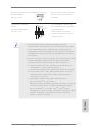
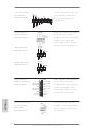
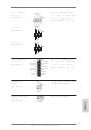
Step 3.
Remove the bracket facing the slot that you intend to use. Keep the
screws for later use.
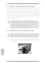
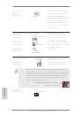
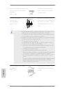
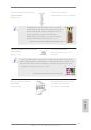
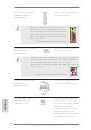
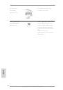
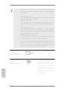
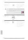
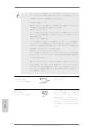
Step 4.
Align the card connector with the slot and press firmly until the card is
completely seated on the slot.
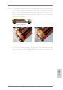
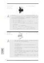
Step 5.
Fasten the card to the chassis with screws.
Step 6.
Replace the system cover.
 1
1
 2
2
 3
3
 4
4
 5
5
 6
6
 7
7
 8
8
 9
9
 10
10
 11
11
 12
12
 13
13
 14
14
 15
15
 16
16
 17
17
 18
18
 19
19
 20
20
 21
21
 22
22
 23
23
 24
24
 25
25
 26
26
 27
27
 28
28
 29
29
 30
30
 31
31
 32
32
 33
33
 34
34
 35
35
 36
36
 37
37
 38
38
 39
39
 40
40
 41
41
 42
42
 43
43
 44
44
 45
45
 46
46
 47
47
 48
48
 49
49
 50
50
 51
51
 52
52
 53
53
 54
54
 55
55
 56
56
 57
57
 58
58
 59
59
 60
60
 61
61
 62
62
 63
63
 64
64
 65
65
 66
66
 67
67
 68
68
 69
69
 70
70
 71
71
 72
72
 73
73
 74
74
 75
75
 76
76
 77
77
 78
78
 79
79
 80
80
 81
81
 82
82
 83
83
 84
84
 85
85
 86
86
 87
87
 88
88
 89
89
 90
90
 91
91
 92
92
 93
93
 94
94
 95
95
 96
96
 97
97
 98
98
 99
99
 100
100
 101
101
 102
102
 103
103
 104
104
 105
105
 106
106
 107
107
 108
108
 109
109
 110
110
 111
111
 112
112
 113
113
 114
114
 115
115
 116
116
 117
117
 118
118
 119
119
 120
120
 121
121
 122
122
 123
123
 124
124
 125
125
 126
126
 127
127
 128
128
 129
129
 130
130
 131
131
 132
132
 133
133
 134
134
 135
135
 136
136
 137
137
 138
138
 139
139
 140
140
 141
141
 142
142
 143
143
 144
144
 145
145
 146
146
 147
147
 148
148
 149
149
 150
150
 151
151
 152
152
 153
153
 154
154
 155
155
 156
156
 157
157
 158
158
 159
159
 160
160
 161
161
 162
162
 163
163
 164
164
 165
165
 166
166
 167
167
 168
168
 169
169
 170
170
 171
171
 172
172
 173
173
 174
174
 175
175
 176
176
 177
177
 178
178
 179
179
 180
180
 181
181
 182
182
 183
183
 184
184
 185
185
 186
186
 187
187
 188
188
 189
189
 190
190
 191
191
 192
192
 193
193
 194
194
 195
195
 196
196
 197
197
 198
198
 199
199
 200
200
 201
201
 202
202
 203
203
 204
204
 205
205
 206
206
 207
207
 208
208
 209
209
 210
210
 211
211
 212
212
 213
213
 214
214
 215
215
 216
216
 217
217
 218
218
 219
219
 220
220
 221
221
 222
222
 223
223
 224
224
 225
225
 226
226
 227
227
 228
228
 229
229
 230
230