ENGLISH
Description
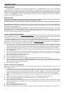
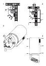
The unit can be found in filtering hoods or ducting hoods.
In the
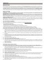
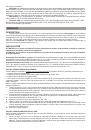
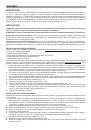
filtering version
the air and the kitchen fumes that are
conveyed by the apparatus are depurated by the charcoal filter and put back into the room through the small grilles of the
ventilation flue (Fig. 1). ATTENTION: When using the filtering version, a charcoal filter and an air baffle (Fig. 1A) must
be used, which placed at the top of the structure, allows the air to recycle back into the room.
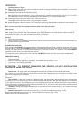
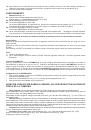
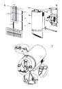
In the
Ducting version
,
cooking vapours and odours are conveyed straight outside by a disposal duct which passes through the ceiling (Fig. 2).
instALLAtion
Attention: to install this appliance at least two people are necessary; therefore the installation work must
be undertaken by a qualified and competent personnel.
WARNING: Do not remove the adhesive tape on the front and side of the hood until you have completed installation.
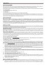
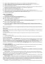
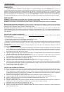
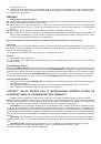
Removing the grease filters:
Before proceeding with the installation operations, remove the grease filters to make
it easier to handle the hood (Fig.3): Open the cover (A), unscrew the knob (B), remove the panel (C), pull the handle
outwards and release the filter.
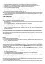
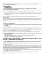
separating the hood parts:
Remove the control box connector (Fig. 7-A), remove the connector of the two halogen
spotlights (Fig. 7-B), remove the sensor box from its seat (Fig. 7-C), separate the outside from the inside by undoing
the 6 screws (Fig. 4), and separate the inside from the wooden panel by undoing the 4 screws.
DUCTING VERSION ASSEMBLY
Before the installation of the appliance, it is necessary to arrange the air disposal duct.
Use a disposal duct which has:
- the minimum necessary length.
- minimum number of curves ( maximum curve corner: 90°).
- material approved by the State legislations; very smooth internal walls.
- Moreover we suggest you to avoid big changes to the pipe section (suggested diameter: 150 mm).
For the external air evacuation, follow all the other indications, as you can see in the “Warning” sheet.
Arrange the electrical feeding (for the electrical connection, follow all the other indications on the “Warning” sheet).
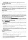
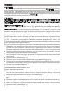
1.
Draw a line on the wall, on the vertical of your cooking hob. Draw on the wall the 6 holes you will make, according
to the measures indicated in the Fig. 5; make the holes and insert the dowels (Issued). As already specified in the
“Warning” sheet , consider that the distance between the hood lower border and the cooking hob must be min 440
mm.
2.
Make the electrical connection. Connect the air exhaust pipe to the flange using a bracket (pipe and bracket not
provided).
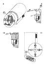
3.
Take the external part of the hood (cylindrical body), remove the polystyrene and slide it in from the front until it
touches the wall, then push it upwards until it touches the ceiling (Fig. 6). Secure it with 6 screws (use the 6 screws
removed previously).
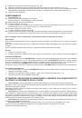
4.
Connect the control box (Fig. 7-A).
5.
Connect the 2 halogen spotlights (Fig. 7-B).
6.
Fit the sensor box its seat, exercising slight pressure (Fig. 7-C).
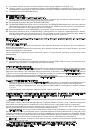
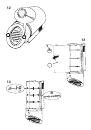
7.
Remember that for the ducting version the charcoal filter is NOT necessary, therefore, if it is installed, proceed with
removing it: grip the charcoal filter clip, push the filter towards the lower edge and then turn it towards the outside
of the hood (Fig. 8).
8.
Refit the grease filter.
FILTERING VERSION INSTALLATION
Arrange the electrical feeding (for the electrical connection, follow all the other indications on the “Warning sheet”.
1.
Draw a line on the wall, on the vertical of your cooking hob. Draw on the wall the 6 holes you will make, according
to the measures indicated in the Fig. 6; make the holes and insert the dowels (Issued).
As already specified in the “Warning” sheet , consider that the distance between the hood lower border and the
cooking hob must be min 440 mm.
2.
Fit the rectangular plate on the internal part, using 4 screws as shown in Fig. 9.
3.
Fit the cable duct (B) in the round slot and run the power cable through it (Fig. 9).
4.
Fit the air baffle above the rectangular plate using 4 screws (Fig. 10).
5.
Make the electrical connection.
6.
Take the external part of the hood (cylindrical body) and slide it in from the front until it touches the wall, then push
it upwards until it touches the ceiling (Fig. 6); Secure it with 6 screws (use the 6 screws removed previously).
7.
Connect the control box (Fig. 7-A).
8.
Connect the 2 halogen spotlights (Fig. 7-B).
9.
Fit the sensor box in its seat, exercising slight pressure (Fig. 7-C).
10.
Remember that for the filtering version the charcoal filter is necessary, therefore, if it is not yet installed, proceed
with installation by resting the filter on the lower edge and then turning it towards the inside of the hood (Fig. 8).
11. Refit the grease filter.