•
Real 1000 W AES power handling
•
Sensitivity: 97 dB @ 2.83V
•
4” duo technology voice coil
•
Forced air convection circuit for low power compression
•
Extended controlled displacement: Xmax ± 8 mm.
•
Massive mechanical displacement capability: 52 mm p-p
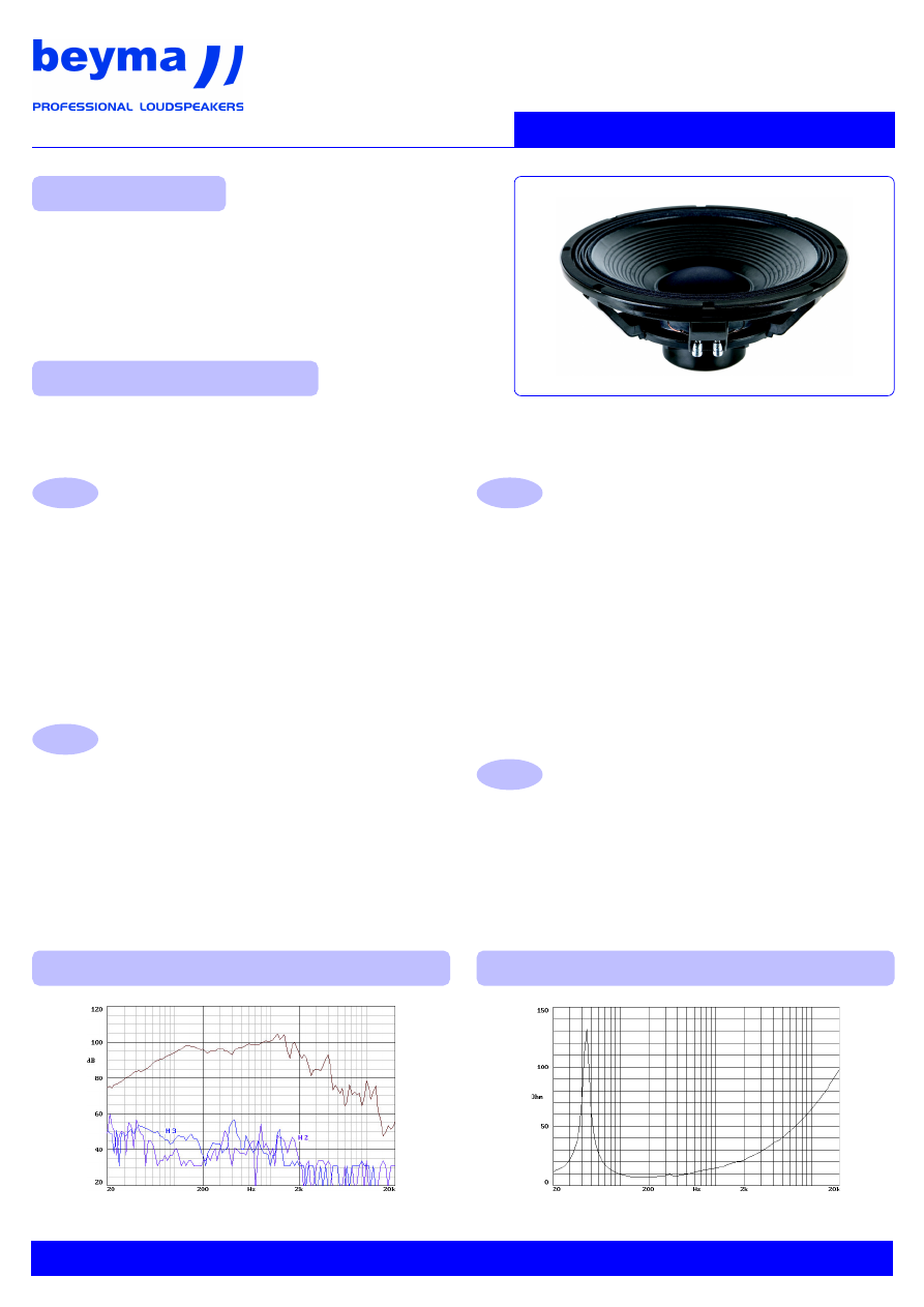
15P1000Nd
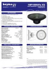
This model is the result of an extensive and intense research of every single constituent part of an electro-dynamic loudspeaker,
rethinking the basics and taking care of every detail, to withstand the extreme power conditions it has been designed to work in.
All this investigation is reflected in the new and innovative technologies developed by Beyma and applied in this new transducer.
Note: on axis frequency response measured with loudspeaker standing
on infinite baffle in anechoic chamber, 1w @ 1m.
15P1000Nd
P1000/Nd Series
DUO TECHNOLOGY 4” VOICE COIL
•
Laminated former combining two different advanced
technology materials to enhance the voice coil life.
•
Voice coil winding coiled over the two faces of the former.
•
Double insulation paper (inner and outer) for optimum for-
ce transmission.
•
Superficial treatment of the voice coil winding to provide
further protection to the voice coil wire.
HEAT DISSIPATION
•
Low power compression due to the use of a forced
convection mechanism.
•
This design has been optimized with the extensive use of
miniature high temperature probes and real-time
temperature acquisition systems, together with a thermo-
graphic camera to obtain real images of the heat
distribution in the voice coil and forced convection effects.
MOVING ASSEMBLY
•
High stiffness weather resistant paper cone.
•
Beyma Double Conex Spider technology (D.C.S.): the
conex is a fireproof material that insures the preservation
of the spider mechanical properties under extreme power
conditions.
•
Beyma Mechanical Mirror Suspension System
(M.M.S.S.): the diaphragm surround and the double
spider have been carefully designed with the assistance of
Finite Element calculations in order to match coherently,
enabling long and controlled cone displacements.
UNDER-POLE NEODYMIUM MAGNET TOPOLOGY
•
F.E.A. optimized under-pole magnet topology. This
geometry maximizes the flux density in the air-gap and
completely eliminate the leakage magnetic field, avoiding
any possible magnetic interference with other equipment.
•
High temperature neodymium magnets.
KEY FEATURES
GENERAL DESCRIPTION
FREE AIR IMPEDANCE CURVE
FREQUENCY RESPONSE AND DISTORTION CURVES
01
16