20
en |
ISP-EMIL-120 LSN Expansion Module
F.01U.076.548 | V3 | 2008.10
Installation manual
Bosch Sicherheitssysteme GmbH
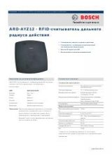
Functional description
The LSN expansion module can be used to connect 6 detector zones (conventional detectors or monitoring
contact inputs), for control purposes (4 control outputs) or for connecting arming devices (e.g. NBS 10) with
system components to the local security network (LSN). The LSN Expansion Module has been developed for
connection to LSN control panels, e.g. MAP 5000, and provides the extended functionality of LSN improved
technology. The LSN mode "classic" can be selected via the integrated DIP switch (default setting), enabling
the connection of all classic LSN emergency call detector control panels such as NZ 300 LSN, UEZ 2000 LSN
and UGM 2020. A maximum of 2 x IMS-RM relay modules can optionally be installed in the expansion module
housing (2 relays per relay module, 2 switch contacts per relay), if the switched control elements cannot be
directly controlled from the expansion module due to the high current requirement, or to enable zero-potential
switching. A wall tamper contact can be installed, if required (optional).
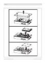
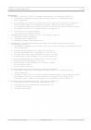
Installation
1.
Installation preparation: see Fig. 1, page 5
2.
Cable entry points: see Fig. 2, page 6
3.
Device base and screw for wall tamper contact (optional): see Fig. 3, page 7
4.
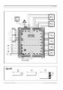
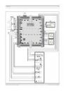
Connection terminals, relay module (optional) and wall tamper contact (optional): see Fig. 4, page 8
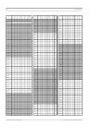
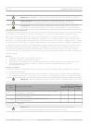
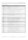
Address setting
The address of the expansion module is set via the 8 DIP switches on the connector board using a suitable
pointed implement.
5.
The DIP switch settings for all permissible addresses are listed in the diagrams and the tables below
(1 = on, 0 = off): see Fig. 5, page 9 and tables below.
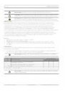
i
NOTE! Installation to be performed by authorized specialized personnel only!
!
WARNING! Current-carrying components and isolated cable. Danger of injury
through electric shock. The system must be free of current when connecting.
CAUTION! Electrostatic discharge (ESD) Electronic components may be damaged.
Attach grounding wrist strap or take other suitable measures.
i
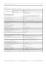
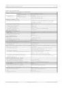
NOTE! The address "255" is set at the factory (all DIP switches set to "on").
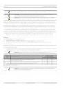
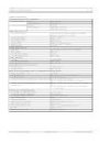
Address
(A)
Operating mode (mode)
Network structure
Loop
Stub
T-branch
255 = CL
Automatic address assignment in "classic" LSN mode.
(Address range: max. 127)
x
x
-
0
Automatic address assignment in "improved version" LSN mode.
x
x
-
1 to 254
Manual address assignment in "improved version" LSN mode.
x
x
x
x = possible, - = not possible
i
NOTE! Different operating modes must not be used next to one another
in loops/stubs/T-branches.


Инструкции и руководства похожие на BOSCH ISP-EMIL-120


Другие инструкции и руководства из категории Охранное оборудование