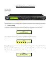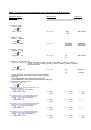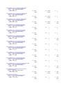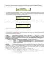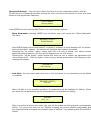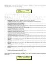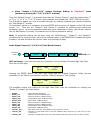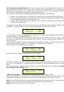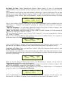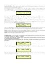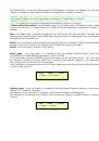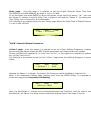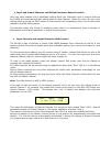
2.1 Output
[x]
[Name]
LPF
->
Y
F = 20.0 Hz
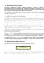
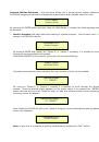
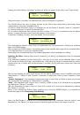
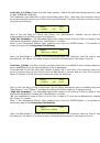
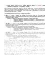
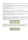
2.1a.
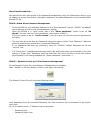
If selected a filter from
Buttw_1st
up to Bessel_4th, then
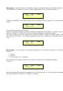
the filter's Cutting Frequency can be set as follow:
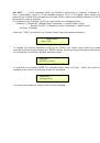
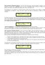
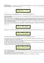
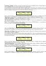
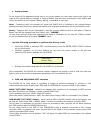
Output
[x]
[Name]
LPF
[Thousands Editor]
[Hundreds Editor] [Units Editor]
->
Edit Freq = 250Hz
[Freq.]
1000Hz
[Freq.]
100Hz
[Freq.]
1Hz
:
:
:
20000Hz
900Hz
100Hz
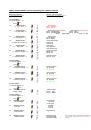
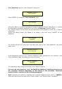
2.1b.
If selected a
Custom Filter
(from 2
nd
up to 4
th
order), depending
from the filter's order, the cascade of second order Cells building
the filter are available for editing in their Freq and Q parameter,
independently.
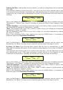
For proceeding with the editing of a custom filter Cell, the Param.1 is
here used for the Cell selection.
So, a Custom Filter can be set in its parameters, as follow:
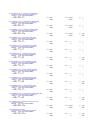
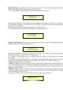
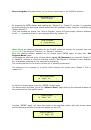
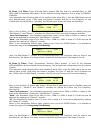
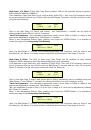
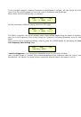
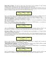
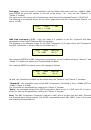
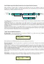
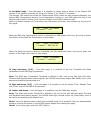
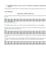
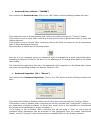
2.1b.1.
If selected a
Custom_2nd
filter
Output
[x]
[Name]
LPF
-
>Custom_2nd F = 250Hz
[2
nd
order Cells selection]
→
Filt
x
F= 250Hz Q = 0.3
[2
nd
Ord Cell
x
]
x=1
[Freq.]
20Hz
[Q]
0.05
:
:
:
x=1
20kHz
10.00
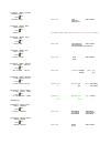
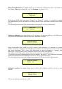
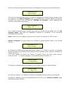
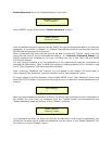
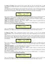
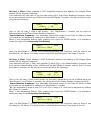
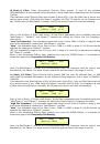
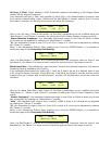
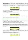
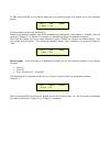
2.1b.2.
If selected a
Custom_3rd
filter
Output
[x]
[Name]
LPF
-
>Custom_3rd F = 250Hz
→
Filt
x
F= 250Hz Q = 0.3
[2
nd
Ord Cell
x
]
x=1
[Freq.]
20Hz
[Q]
0.05
:
:
:
[Q not available]
x=2
20kHz
10.00
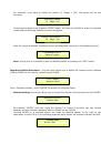
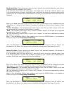
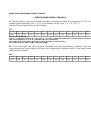
2.1b.3.
If selected a
Custom_4th
filter
Output
[x]
[Name]
LPF
-
>Custom_4th F = 250Hz
→
Filt
x
F= 250Hz Q = 0.3
[2
nd
Ord Cell
x
]
x=1
[Freq.]
20Hz
[Q]
0.05
:
:
:
x=2
20kHz
10.00
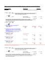
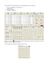
Once editing the Cells “Filtx”, pressing the Enter Button can be accessed also for the Custom Filters the page for the fast frequency setting, as available for the NOT Custom
Filters and which way of working is described at the point 1.1a.
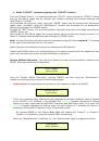
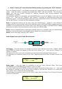
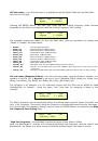
3. Out-[x]
EQ-[x] (X from 1 to 5)
Byp = Off Type = Y (Y = Peaking_Eq, Hi-Shelv_1, Hi-Shelv_2, Hi-Shelv_Q, Lo-Shelv_1, Lo-Shelv_2, Lo-Shelv_Q,
Lo-Pass_1, Lo-Pass_2, Lo-Pass_Q, Hi-Pass_1, Hi-Pass_2, Hi-Pass_Q, All Pass_1, All Pass_2,
Band Pass, Notch Filt)
->
Byp = Off Type = Y
Param.1 N/A
Off
Peaking_Eq
:
:
On
Notch Filt
Through the Param.2, it is possible to Byp the single selected filter.
Through the Param.3, it is possible to select one of the 17 available
filters' type.
Once selected the filter Type and NOT in Byp mode, pressing
again the ENTER button can be accessed the selected filter's editing page.
3.1 Out-[x]
EQ-[x] (X from 1 to 5)
->
Byp = Off Type =
Y
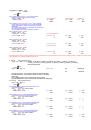
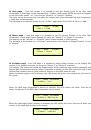
3.1a.
If selected a
Peaking_Eq
filter, then the filter can be set by
the following parameters
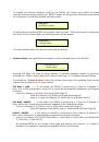
Out-[x]
EQ-[x] (up to 5 filters available)
[Freq] [Gain] [Q]
->
1000Hz +0.0dB Q=1.00
[Freq.]
20Hz
[Amp.]
-15.0 dB
[Q]
0.30
:
:
:
20kHz
+15.0 dB
20.00
3.1b.
If selected a
Hi-Shelv_1
(first order High Shelving) filter,
then the filter can be set by the following parameters
Out-[x]
EQ-[x] (up to 5 filters available)
[Freq] [Gain] [Q]
->
1000Hz +0.0dB Q= ----
[Freq.]
20Hz
[Amp.]
-15.0 dB
[Q]
----
:
:
:
20kHz
+15.0 dB
----
3.1c.
If selected a
Hi-Shelv_2
(second order High Shelving) filter,
then the filter can be set by the following parameters
Out-[x]
EQ-[x] (up to 5 filters available)
[Freq] [Gain] [Q]
->
1000Hz +0.0dB Q= ----
[Freq.]
20Hz
[Amp.]
-15.0 dB
[Q]
----
:
:
:
20kHz
+15.0 dB
----
3.1d.
If selected a
Hi-Shelv_Q
(variable Q High Shelving) filter,
then the filter can be set by the following parameters
Out-[x]
EQ-[x] (up to 5 filters available)
[Freq] [Gain] [Q]
->
1000Hz +0.0dB Q=1.00
[Freq.]
20Hz
[Amp.]
-15.0 dB
[Q]
0.30
:
:
:
20kHz
+15.0 dB
20.00
ENTER
ESC
ENTER
ESC
ENTER
ESC