Доступность: Бесплатно как и все руководства на сайте. Без регистрации и SMS.
Дополнительно: Чтение инструкции онлайн
Appendix
- 69 -
English
Страница: (69 из 72)
навигация
1
2
3
4
5
6
7
8
9
10
11
12
13
14
15
16
17
18
19
20
21
22
23
24
25
26
27
28
29
30
31
32
33
34
35
36
37
38
39
40
41
42
43
44
45
46
47
48
49
50
51
52
53
54
55
56
57
58
59
60
61
62
63
64
65
66
67
68
69
70
71
72
Оглавление инструкции
Страница 1 из 73 GA-8I865GME Intel® Pentium® 4 Processor Motherboard User's Manual Rev. 1001 12ME-865GME-1001R * The WEEE marking on the product indicates this product must not be disposed of with user's other household waste and must be handed over to a designated collection point for the recycling of waste
Страница 9 из 73 1-1 English Chapter 1 Hardware Installation Considerations Prior to Installation Preparing Your Computer The motherboard contains numerous delicate electronic circuits and components which can become damaged as a result of electrostatic discharge (ESD). Thus, prior to installation, please follow
Страница 10 из 73 English 1-2 Feature Summary CPU Front Side Bus Chipset LAN Audio Storage O.S Support Memory Expanstion Slots Internal Connectors Socket 478 for Intel ® Pentium ® 4 (Northwood, Prescott) with HT Technology L2 cache varies with CPU Supports 800/533/400MHz FSB Northbridge: Intel ® 865G Chipset
Страница 11 из 73 I/O Control Hardware Monitor BIOS Additional Features Bundle Software Form Factor (Note) 1 PS/2 keyboard port 1 PS/2 mouse port 1 parallel port 1 VGA port 1 COMA port 4 USB 2.0/1.1 ports 1 RJ-45 port 3 audio jacks (Line In / Line Out / MIC In) IT8712 chip System voltage detection CPU temperature
Страница 12 из 73 English 1-3 Installation of the CPU and Heatsink Before installing the CPU, please comply with the following conditions: 1. Please make sure that the motherboard supports the CPU. 2. Please take note of the one indented corner of the CPU. If you install the CPU in the wrong direction, the CPU will
Страница 13 из 73 Fig.1 Before installing the heat sink, please first add an even layer of heat sink paste on the surface of the CPU. Install all the heat sink components (Please refer to the heat sink manual for detailed installation instructions). Fig.2 Please connect the heat sink power connector to the CPU_FAN
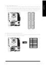
Страница 14 из 73 English 1-4 Installation of Memory Before installing the memory modules, please comply with the following conditions: 1. Please make sure that the memory used is supported by the motherboard. It is recommended that memory of similar capacity, specifications and brand be used. 2. Before installing
Страница 15 из 73 The GA-8I865GME supports the Dual Channel Technology. When the Dual Channel Technology is activated, the bandwidth of memory bus will be double the original one. The GA-8I865GME includes 2 DIMM sockets, and each Channel has one DIMM socket as following: Channel A : DDR 1 Channel B : DDR 2 If you
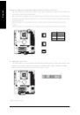
Страница 16 из 73 English 1-5 Installation of Expansion Cards You can install your expansion card by following the steps outlined below: 1. Read the related expansion card's instruction document before install the expansion card into the computer. 2. Remove your computer's chassis cover, screws and slot bracket from
Страница 17 из 73 I/O Back Panel Introduction English 1-6 PS/2 Keyboard and PS/2 Mouse Connector To install a PS/2 port keyboard and mouse, plug the mouse to the upper port (green) and the keyboard to the lower port (purple). Parallel Port The parallel port allows connection of a printer, scanner and other
Страница 19 из 73 ATX_12V/ATX (Power Connector) With the use of the power connector, the power supply can supply enough stable power to all the components on the motherboard. Before connecting the power connector, please make sure that all components and devices are properly installed. Align the power connector with
Страница 20 из 73 English 3/4/5) CPU_FAN / SYS_FAN / PWR_FAN* (Cooler Fan Power Connector) The cooler fan power connector supplies a +12V power voltage via a 3-pin power connector and possesses a foolproof connection design. Most coolers are designed with color-coded power connector wires. A red power connector wire
Страница 21 из 73 An IDE device connects to the computer via an IDE connector. One IDE connector can connect to one IDE cable, and the single IDE cable can then connect to two IDE devices (hard drive or optical drive). If you wish to connect two IDE devices, please set the jumper on one IDE device as Master and the
Страница 22 из 73 English 9) PWR_LED PWR_LED is connect with the system power indicator to indicate whether the system is on/off. It will blink when the system enters suspend mode. Pin No. Definition 1 MPD+ 2 3 1 MPDMPD- 10) BATTERY Danger of explosion if battery is incorrectly replaced. Replace only with the same
Страница 23 из 73 Please connect the power LED, PC speaker, reset switch and power switch etc. of your chassis front panel to the F_PANEL connector according to the pin assignment below. Speaker Connector 2 1 SPEAK- MSG+ MSGPW+ PW- Power Switch SPEAK+ Message LED/ Power/ Sleep LED RES+ NC HD+ RES- HD- 20 19 Reset
Страница 24 из 73 English 12) F_AUDIO (Front Audio Panel Connector) If you want to use Front Audio connector, you must remove 5-6, 9-10 Jumper. In order to utilize the front audio header, your chassis must have front audio connector. Also please make sure the pin assignments for the cable are the same as the pin
Страница 25 из 73 Be careful with the polarity of the front USB connector. Check the pin assignment carefully while you connect the front USB cable, incorrect connection between the cable and connector will make the device unable to work or even damage it. For optional front USB cable, please contact your local
Страница 26 из 73 English 16) CLR_CMOS (Clear CMOS) You may clear the CMOS data to its default values by this header. To clear CMOS, temporarily short the two pins. Default doesn't include the jumper to avoid improper use of this header. Open: Normal Short: Clear CMOS 17) BIOS_WP (BIOS Write Protection)* This header
Страница 27 из 73 BIOS (Basic Input and Output System) includes a CMOS SETUP utility which allows user to configure required settings or to activate certain system features. The CMOS SETUP saves the configuration in the CMOS SRAM of the motherboard. When the power is turned off, the battery on the motherboard
Страница 28 из 73 English <F12> : For Boot Menu Select boot sequence for onboard (or add-on cards) device. Award Modular BIOS v6.00PG, An Energy Star Ally Copyright (C) 1984-2006, Award Software, Inc. Intel 865G AGPSet BIOS for 8I865GME D1 . . . . <DEL>:BIOS Setup/Q-Flash, <F9>: Xpress Recovery2, <F12>For Boot Menu
Страница 29 из 73 English Standard CMOS Features This setup page includes all the items in standard compatible BIOS. Advanced BIOS Features This setup page includes all the items of Award special enhanced features. Integrated Peripherals This setup page includes all onboard peripherals. Power Management Setup This
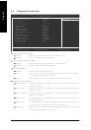
Страница 30 из 73 English 2-1 Standard CMOS Features CMOS Setup Utility-Copyright (C) 1984-2006 Award Software Standard CMOS Features Date (mm:dd:yy) Time (hh:mm:ss) Tue, Mar 28 2006 22:31:24 Item Help Menu Level IDE Channel 0 Master IDE Channel 0 Slave IDE Channel 1 Master IDE Channel 1 Slave IDE Channel 2 Master
Страница 31 из 73 Drive A / Drive B The category identifies the types of floppy disk drive A or drive B that has been installed in the computer. None No floppy drive installed 360K, 5.25" 5.25 inch PC-type standard drive; 360K byte capacity. 1.2M, 5.25" 5.25 inch AT-type high-density drive; 1.2M byte capacity (3.5
Страница 32 из 73 English 2-2 Advanced BIOS Features CMOS Setup Utility-Copyright (C) 1984-2006 Award Software Advanced BIOS Features Hard Disk Boot Priority First Boot Device Second Boot Device Third Boot Device Password Check # CPU Hyper-Threading Limit CPUID Max. to 3 Init Display First On-Chip Frame Buffer Size
Страница 33 из 73 Enabled Disabled Enable CPU Hyper-Threading Feature. Please note that this feature is only working for operating system with multi processors mode supported. (Default value) Disable CPU Hyper-Threading. Limit CPUID Max. to 3 Enabled Disabled Limit CPUID Maximum value to 3 when use older OS like
Страница 34 из 73 English 2-3 Integrated Peripherals CMOS Setup Utility-Copyright (C) 1984-2006 Award Software Integrated Peripherals On-Chip Primary PCI IDE On-Chip Secondary PCI IDE On-Chip SATA x SATA Port0 configure as SATA Port1 configure as USB Controller USB 2.0 Controller USB Keyboard Support USB Mouse
Страница 35 из 73 The setting depends on "SATA Port0 configure as" item setting. (Default: SATA Port1) USB Controller Enabled Disabled Enable USB controller. (Default value) Disable USB controller. USB 2.0 Controller You can disable this function if you are not using onboard USB 2.0 feature. Enabled Enable USB 2.0
Страница 36 из 73 English Parallel Port Mode SPP EPP ECP ECP+EPP Using Parallel port as Standard Parallel Port. (Default value) Using Parallel port as Enhanced Parallel Port. Using Parallel port as Extended Capabilities Port. Using Parallel port as ECP and EPP mode. ECP Mode Use DMA 3 1 Set ECP Mode Use DMA to 3.
Страница 37 из 73 Power Management Setup English 2-4 CMOS Setup Utility-Copyright (C) 1984-2006 Award Software Power Management Setup ACPI Suspend Type Power LED in S1 state Off by Power button PME Event Wake Up ModemRingOn/WakeOnLan Resume by Alarm x Date (of Month) Alarm x Time (hh:mm:ss) Alarm Power On By Mouse
Страница 38 из 73 English Power On By Mouse Disabled Enable Disabled this function. (Default value) Double click on PS/2 mouse left button to power on the system. Power On By Keyboard Disabled Disabled this function. (Default value) Password Enter from 1 to 5 characters to set the Keyboard Power On Password.
Страница 39 из 73 PC Health Status CMOS Setup Utility-Copyright (C) 1984-2006 Award Software PC Health Status Reset Case Open Status Case Opened VCORE DDR25V +3.3V +12V Current CPU Temperature Current CPU FAN Speed Current SYSTEM FAN Speed CPU Warning Temperature CPU FAN Fail Warning SYSTEM FAN Fail Warning : Move
Страница 40 из 73 English 2-7 Frequency/Voltage Control CMOS Setup Utility-Copyright (C) 1984-2006 Award Software Frequency/Voltage Control CPU Clock Ratio Memory Frequency For Memory Frequency (Mhz) [21X] [Auto] 266 Item Help Menu Level Set CPU Ratio if CPU Ratio is unclocked : Move Enter: Select F5: Previous
Страница 41 из 73 Load Fail-Safe Defaults English 2-8 CMOS Setup Utility-Copyright (C) 1984-2006 Award Software Standard CMOS Features Load Fail-Safe Defaults Advanced BIOS Features Integrated Peripherals Load Optimized Defaults Set Supervisor Password Power Management Setup PnP/PCI Configurations Set User Password
Страница 42 из 73 English 2-10 Set Supervisor/User Password CMOS Setup Utility-Copyright (C) 1984-2006 Award Software Standard CMOS Features Load Fail-Safe Defaults Advanced BIOS Features Integrated Peripherals Load Optimized Defaults Set Supervisor Password Power Management Setup PnP/PCI Configurations Enter
Страница 43 из 73 English 2-11 Save & Exit Setup CMOS Setup Utility-Copyright (C) 1984-2006 Award Software Standard CMOS Features Load Fail-Safe Defaults Advanced BIOS Features Integrated Peripherals Load Optimized Defaults Set Supervisor Password Power Management Setup PnP/PCI Configurations Set User Password Save
Страница 45 из 73 Pictures below are shown in Windows XP. Insert the driver CD-title that came with your motherboard into your CD-ROM drive, the driver CD-title will auto start and show the installation guide. If not, please double click the CD-ROM device icon in "My computer", and execute the Setup.exe. 3-1 Install
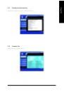
Страница 46 из 73 English 3-2 Software Application This page displays all the tools that GIGABYTE developed and some free software. You can click an item to install it. 3-3 Software Information This page lists the contents of software and drivers in this CD-title. GA-8I865GME Motherboard - 46 -
Страница 47 из 73 Hardware Information English 3-4 This page lists all device you have for this motherboard. 3-5 Contact Us Please see the last page for details. - 47 - Drivers Installation
Страница 49 из 73 4-1 English Chapter 4 Appendix Unique Software Utilities 4-1-1 EasyTune 5 Introduction EasyTune 5 presents the most convenient Windows based system performance enhancement and manageability utility. Featuring several powerful yet easy to use tools such as 1) Overclocking for enhancing system
Страница 50 из 73 English 4-1-2 Xpress Recovery2 Introduction Xpress Recovery2 is designed to provide quick backup and restoration of hard disk data. Supporting Microsoft operating systems including Windows XP/2000/NT/98/Me and DOS, and file systems including FAT16, FAT32, and NTFS, Xpress Recovery2 is able to back
Страница 51 из 73 1. RESTORE: Restore the backed-up data to your hard disk. (This button will not appear if there is no backup file.) 2. BACKUP: Back up data from hard disk. 3. REMOVE: Remove previously-created backup files to release disk space. (This button will not appear if there is no backup file.) 4. REBOOT:
Страница 52 из 73 English 4-1-3 Flash BIOS Method Introduction Method 1 : Q-FlashTM Utility Q-Flash TM is a BIOS flash utility embedded in Flash ROM. With this utility, users only have to stay in the BIOS menu when they want to update BIOS. Q-Flash TM allows users to flash BIOS without any utility in DOS or TM
Страница 53 из 73 English Entering the Q-FlashTM utility: Step1: To use Q-Flash utility, you must press Del in the boot screen to enter BIOS menu. CMOS Setup Utility-Copyright (C) 1984-2004 Award Software Standard CMOS Features Advanced BIOS Features Select Language Load Fail-Safe Defaults Integrated Peripherals
Страница 54 из 73 English Using the Q-FlashTM utility: This section tells you how to update BIOS using the Q-Flash utility. As described in the "Before you begin" section above, you must prepare a floppy disk having the BIOS file for your motherboard and insert it to your computer. If you have already put the floppy
Страница 55 из 73 English 3. Press Y button on your keyboard after you are sure to update BIOS. Then it will begin to update BIOS. The progress of updating BIOS will be displayed. Please do not take out the floppy disk when it begins flashing BIOS. 4. Press any keys to return to the Q-Flash menu when the BIOS
Страница 56 из 73 English 6. Press Del to enter BIOS menu after system reboots. When you are in BIOS menu, move to Load Optimized Defaults item and press Enter to load BIOS Fail-Safe Defaults. Normally the system redetects all devices after BIOS has been upgraded. Therefore, we highly recommend reloading the BIOS
Страница 57 из 73 The Q-FlashBIOS utility screen consists of the following key components. Q-FlashTM utility bar Q-Flash Utility V1.30 Flash Type/Size.................................SST 49LF003A Task menu for Q-FlashTM utility Enter : Run Keep DMI Data Enable Update BIOS from Floppy Save BIOS to Floppy :Move
Страница 58 из 73 English 3. Press Y button on your keyboard after you are sure to update BIOS. Then it will begin to update BIOS. The progress of updating BIOS will be shown at the same time. Q-Flash Utility V1.30 Flash Type/Size.................................SST 49LF003A 256K Keep DMI Data BIOS Now Updating
Страница 59 из 73 If you do not have a DOS startup disk, we recommend that you use the new @BIOS utility. @BIOS allows users to update their BIOS under Windows. Just select the desired @BIOS server to download the latest version of BIOS. Fig 1. Installing the @BIOS utility Fig 2. Installation complete and run @BIOS
Страница 60 из 73 English III. Save BIOS: In the very beginning, there is "Save Current BIOS" icon shown in dialog box. It means to save the current BIOS version. IV. Check out supported motherboard and Flash ROM: In the very beginning, there is "About this program" icon shown in dialog box. It can help you check
Страница 61 из 73 The installation of audio software for Windows 2000/ XP is very simple. Please follow the steps to install the function. (Following pictures are in Windows XP) Stereo Speakers Connection and Settings: We recommend that you use the speaker with amplifier to acquire the best sound effect if the
Страница 62 из 73 English 4 Channel Audio Setup STEP 1: Connect the Front Speakers to "Line Out", the Rear Speakers to "Line In". Line In (Rear Speaker Out) Line Out (Front Speaker Out) STEP 2: Following installation of the audio driver, you'll find a Sound Effect icon on the lower right hand taskbar. Click the icon
Страница 63 из 73 English 6 Channel Audio Setup STEP 1: Connect the Front Speakers to "Line Out", the Rear Speakers to "Line In", and the Center/Subwoofer Speakers to "MIC In". Line In (Rear Speaker Out) Line Out (Front Speaker Out) Mic In (Center/Subwoofer Speaker Out) STEP 2: Following installation of the audio
Страница 64 из 73 English 4-2 Troubleshooting Below is a collection of general asked questions. To check general asked questions based on a specific motherboard model, please log on to http://www.gigabyte.com.tw Question 1: I cannot see some options that were included in previous BIOS after updating BIOS. Why?
Страница 71 из 73 English Contact Us Taiwan (Headquarters) Japan GIGA-BYTE TECHNOLOGY CO., LTD. NIPPON GIGA-BYTE CORPORATION Address: No.6, Bau Chiang Road, Hsin-Tien, Taipei 231, WEB address : http://www.gigabyte.co.jp Taiwan TEL: +886-2-8912-4888 Singapore GIGA-BYTE SINGAPORE PTE. LTD. FAX: +886-2-8912-4003 Tech.
Страница 72 из 73 English China Russia NINGBO G.B.T. TECH. TRADING CO., LTD. Moscow Representative Office Of GIGA-BYTE Technology Co., Tech. Support : http://www.gigabyte.com.tw/Support/ServiceCenter.aspx Ltd. Tech. Support : Non-Tech. Support(Sales/Marketing) : http://www.gigabyte.com.tw/Support/ServiceCenter.aspx