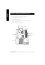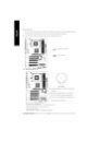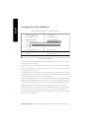
When you installing AGP card, please make sure the follow
ing notice is fully understood and practiced. If your AGP
card has "AGP 4X notch"(show below), please make sure
your AGP card is AGP 4X (1.5V).
Caution: AGP 2X(3.3V) card is not supported by Intel
®
845
(E/G)/ Intel
®
850(E) . You might experience system unable to
boot up normally. Please insert an AGP 4X(1.5V) card
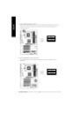
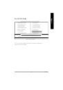
Example 1: Diamond Vipper V770 golden finger is compatible
with 2X/4X mode AGP slot. It can be switched between AGP 2X
(3.3V) or 4X(1.5V) mode by adjusting the jumper. The factory
default for this card is 2X(3.3V).
The
GA-8IE800
(or any AGP 4X
only) motherboards might not function properly, if you install this card
without switching the jumper to 4X(1.5) mode in it.
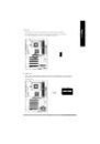
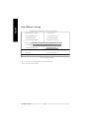
Example 2: Some ATi Rage 128 Pro graphics cards made by
"Power Color", the graphics card manufacturer & some SiS 305
cards, their golden finger is compatible with 2X/4X mode AGP
slot, but they support 2X(3.3V) only.
The
GA-8IE800
(or any AGP
4X only) motherboards might not function properly, If you install this
card in it.
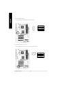
Note : Although Gigabyte's AG32S(G) graphics card is based on
ATi Rage 128 Pro chip, the design of AG32S(G) is compliance
with AGP 4X (1.5V) specification. Therefore, AG32S (G)will work
fine with Intel
®
845(E/G) / 850(E) based motherboards.