Доступность: Бесплатно как и все руководства на сайте. Без регистрации и SMS.
Дополнительно: Чтение инструкции онлайн
- 89 -
English
Memo
Страница: (93 из 96)
навигация
1
2
3
4
5
6
7
8
9
10
11
12
13
14
15
16
17
18
19
20
21
22
23
24
25
26
27
28
29
30
31
32
33
34
35
36
37
38
39
40
41
42
43
44
45
46
47
48
49
50
51
52
53
54
55
56
57
58
59
60
61
62
63
64
65
66
67
68
69
70
71
72
73
74
75
76
77
78
79
80
81
82
83
84
85
86
87
88
89
90
91
92
93
94
95
96
Оглавление инструкции
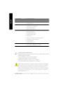
Страница 1 из 97 When you installing AGP card, please make sure the follow ing notice is fully understood and practiced. If your AGP card has "AGP 4X notch"(show below), please make sure your AGP card is AGP 4X (1.5V). Caution: AGP 2X(3.3V) card is not supported by Intel® 845 (E/G)/ Intel® 850(E) . You might
Страница 2 из 97 M The author assumes no responsibility for any errors or omissions that may appear in this document nor does the author make a commitment to update the information contained herein. M Third-party brands and names are the property of theirrespective owners. M Please do not remove any labels on
Страница 3 из 97 Declaration of Conformity We, Manufacturer/Importer (full address) G.B.T. Technology Träding GMbH Ausschlager Weg 41, 1F, 20537 Ham burg, Germany declare that the product ( description of the apparatus, sy stem, installation to w hich it refers) Mother Boa rd GA-8IE800 is in conformity with
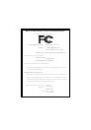
Страница 4 из 97 DECLARATION OF CONFORMITY Per FCC Part 2 Section 2.1077(a) Responsible PartName: Address: G.B.T. INC. (U.S.A.) 17358 Railroad Street City of Industry, CA 91748 Phone/Fax No: (818) 854-9338/ (818) 854-9339 hereby declares that the product Product Name: Motherboard Model Number:GA-8IE800 Conforms to
Страница 6 из 97 English Table of Content Item Checklist .....................................................................................4 WARNING! ..........................................................................................4 Chapter 1 Introduction
Страница 7 из 97 PnP/PCI Configurations................................................................................. 40 PC Health Status ........................................................................................... 41 Frequency/Voltage Control
Страница 8 из 97 English Item Checklist þ þ þ þ o þ o The GA-8IE800 motherboard IDE cable x 2/ Floppy cable x 1 CD for motherboard driver & utility (IUCD) GA-8IE800 user’ manual s I/O Shield Quick PC Installation Guide RAID Manual 2 Port USB Cable x 1 4 Port USB Cable x 1 SPDIF KIT x 1(SPD-KIT) IEEE 1394 Cable x1
Страница 9 из 97 Features Summary Form Factor CPU — 29.3cm x 20.0cm ATX size form factor, 4 layers PCB. — Socket 478 for Intel® Micro FC-PGA2 Pentium® 4 processor — Intel Pentium® 4 533MHz/400MHz FSB — Support Intel ® Pentium ® 4 (Northwood, 0.13 m) processor Chipset Memory I/O Control Slots On-Board IDE On-Board
Страница 10 из 97 English On-Board USB 2.0 — Built in ICH4 Chipset PS/2 Connector BIOS — — — — — — — — PS/2 Keyboard interface and PS/2 Mouse interace Licensed AWARD BIOS, 2M bit Supports Q-Flash CPU/System Fan Revolution detect CPU/System Fan Fail Warning CPU Overheat Warning System Voltage Detect PS/2 Keyboard
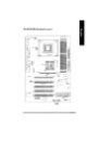
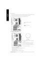
Страница 11 из 97 DDR3 ATX USB DDR2 DDR1 CPU_FAN KB_MS English GA-8IE800 Motherboard Layout LPT1 COMA ATX_12V CD_IN FLOPPY GA-8IE800 F_AUDIO Intel 845E GAME AGP 2X_DET AC 97 BAT PCI1 CLR_PWD SUR_CEN SYS_FAN MIC_IN LINE_OUT LINE_IN COMB SOC KET478 PCI2 P4 Titan ICH4 PCI3 CI PCI4 IDE2 I T8712 PCI5 IDE1 PWR_LED AUX_IN
Страница 12 из 97 English Chapter 2 Hardware Installation Process To set up your computer, you must complete the following steps: Step 1- Install the Central Processing Unit (CPU) Step 2- Install memory modules Step 3- Install expansion cards Step 4- Connect ribbon cables, cabinet wires, and power supply Step 5-
Страница 13 из 97 Step 1-1: CPU Installation Angling the rod to 650 Socket Actuation Lever 2. Pull the rod to the 90-degree directly. 1. Angling the rod to 65-degree maybe feel a kind of tight , and then continue pull the rod to 90-degree when a noise “ cough” made. Pin1 indicator Pin1 indicator 4. Locate Pin 1 in
Страница 14 из 97 English Step 1-2 : CPU Heat Sink Installation 2. Make sure the CPU fan is plugged to the CPU fan connector, than install complete. 1. Fasten the heatsink supporting-base onto the CPU socket on the mainboard. M Please use Intel approved cooling fan. M We recommend you to apply the thermal tape to
Страница 15 из 97 The motherboard has 3 dual inline memory module (DIMM) sockets, but it can only support a maximum of 4 banks of DDR memory. DDR sockets 1 uses 2 banks, DDR sockets 2&3 share the remaining 2 banks. Please refer to the following tables for possible memory configurations supported. The BIOS will
Страница 16 из 97 English Step 3: Install expansion cards 1. Read the related expansion card’ instruction document before install the expansion card into s the computer. 2. Remove your computer’ chassis cover, necessary screws and slot bracket from the computer. s 3. Press the expansion card firmly into expansion
Страница 17 из 97 supply Step 4-1 : I/O Back Panel Introduction w u x v y u PS/2 Keyboard and PS/2 Mouse Connector PS/2 Mouse Connector (6 pin Female) ØThis connector supports standard PS/2 keyboard and PS/2 mouse. PS/2 Keyboard Connector (6 pin Female) v USB Connector USB 1 USB 0 Ø Before you connect your device(s)
Страница 18 из 97 English w Parallel Port ,VGA port and Serial Ports (COMA) Parallel Port (25 pin Female) Ø This connector supports 2 standard COM ports and 1 Parallel port. Device like printer can be connected to Parallel port ; mouse and modem etc can be connected to Serial ports. COMA COMB Serial Ports (9 pin
Страница 20 из 97 English 1) CPU_FAN (CPU FAN Connector) Please note, a proper installation of the CPU cooler is essential to prevent the CPU from running under abnormal condition or damaged by overheating.The CPU fan connector supports Max. current up to 600 mA. 1 Pin No. 1 2 3 Definition GND +12V Sense 2) SYS_FAN
Страница 21 из 97 This connector (ATX _12V) suppliesthe CPU operation voltage (Vcore). If this " ATX_ 12V connector" is not connected, system cannot boot. 4 2 3 1 Pin No. 1 2 3 4 Definition GND GND +12V +12V 4) ATX_POWER (ATX Power) AC power cord should only be connected to your power supply unit after ATX power
Страница 22 из 97 English 5) IDE1/ IDE2(IDE1/IDE2 Connector) Please connect first harddisk to IDE1 and connect CDROM to IDE2. The red stripe of the ribbon cable must be the same side with the Pin1. 40 2 IDE2 IDE1 39 1 6) FDD (Floppy Connector) Please connect the floppy drive ribbon cables to FDD. It supports
Страница 23 из 97 When an AGP 2X (3.3V) card is installed the 2X_DET will light up, indicating a nonsupported graphics card is inserted. Informing users that system might not boot up normally due to AGP 2X (3.3V) is not supported by the chipset. + - 8) PWR_LED PWR_LED is connect with the system power indicator to
Страница 24 из 97 English 9) F_PANEL (2x10 pins connector) Please connect the power LED, PC peaker, reset switch and power switch etc of your chassis front panel to the F_PANEL connector according to the pin assignment above. Soft Po wer Speaker Connector Me ssa g e LED /Po w e r / Connector Sleep LED PW MPD MPD + 1
Страница 25 из 97 The SPDIF output is capable of providing digital audio to external speakers or compressed AC3 data to an external Dolby Digital Decoder. Use this feature only when your stereo system has digital input function. Use SPDIF IN feature only when your device has digital output function. 2 6 1 5 Pin No.
Страница 26 из 97 English 13) CD_IN (CD IN,Blank) Connect CD-ROM or DVD-ROM audio out to the connector. Pin No. 1 2 3 4 1 Definition CD-L GND GND CD_R 14) AUX_IN ( AUX In Connector) Connect other device(such as PCI TV Tunner audio out)to the connector. 1 GA-8IE800 Motherboard - 22 - Pin No. 1 2 3 4 Definition AUX-L
Страница 27 из 97 If you want to use Front Audio connector, you must remove 5-6, 9-10 Jumper. In order to utilize the front audio header, your chassis must have front audio connector. Also please make sure the pin assigment on the cable is the same as the pin assigment on the MB header. To find out if the chassis
Страница 28 из 97 English 17) CLR_PWD When Jumper is set to "open" and system is restarted, the password that is set will be cleared. On the contrary when Jumper is set to "close", the current status remains M PS, the function offers a solution for users who forget the password. 1 open: Clear password 1 close:
Страница 29 из 97 BIOS Setup is an overview of the BIOS Setup Program. The program that allows users to modify the basic system configuration. This type of information is stored in battery-backed CMOS RAM so that it retains the Setup information when the power is turned off. ENTERING SETUP After power on the
Страница 30 из 97 English GETTING HELP Main Menu The on-line description of the highlighted setup function is displayed at the bottom of the screen. Status Page Setup Menu / Option P age Setup Menu Press F1 to pop up a small help window that describes the appropriate keys to use and the possible selections for the
Страница 31 из 97 Integrated Peripherals English l This setup page includes all onboard peripherals. l Power Management Setup l PnP/PCI Configurations This setup page includes all the items of Green function features. This setup page includes all the configurations of PCI & PnP ISA resources. l PC Health Status l
Страница 32 из 97 English Standard CMOS Features CMOS Setup Utility-Copyright (C) 1984-2003 Award Software Standard CMOS Features Date (mm:dd:yy) Thu, Feb 21 2002 Item Help Time(hh:mm:ss) 22:31:24 Menu Level u }IDE Primary Master [Press Enter None] Change the day, month, }IDE Primary Slave [Press Enter None] year
Страница 33 из 97 The category identifies the types of hard disk from drive C to F that has been installed in the computer. There are two types: auto type, and manual type. Manual type is user-definable; Auto type which will automatically detect HDD type. Note that the specifications of your drive must match with
Страница 34 из 97 English FHalt on The category determines whether the computer will stop if an error is detected during power up. 8NO Errors The system boot will not stop for any error that may be detected and you will be prompted. 8All Errors Whenever the BIOS detects a non-fatal error the system will be stopped.
Страница 35 из 97 English Advanced BIOS Features CMOS Setup Utility-Copyright (C) 1984-2003 Award Software Advanced BIOS Features First Boot Device [Floppy] Item Help Second Boot Device [HDD-0] Menu Level Third Boot Device [CDROM] Boot Up Floppy Seek [Disabled] Password Check [Setup] #CPU Hyper-Threading [Enabled]*
Страница 36 из 97 English FBoot Up Floppy Seek During POST, BIOS will determine the floppy disk drive installed is 40 or 80 tracks. 360 K type is 40 tracks 720 K, 1.2 M and 1.44 M are all 80 tracks. 8Enabled BIOS searches for floppy disk drive to determine it is 40 or 80 tracks. Note that BIOS can not tell from 720
Страница 37 из 97 English Integrated Peripherals CMOS Setup Utility-Copyright (C) 1984-2003 Award Software Integrated Peripherals On-Chip Primary PCI IDE [Enabled] Item Help On-Chip Secondary PCI IDE [Enabled] Menu Level IDE1 Conductor Cable [Auto] IDE2 Conductor Cable [Auto] USB Controller [Enabled] USB Keyboard
Страница 38 из 97 English FOn-Chip P rimary PCI IDE When enabled, allows you to use the onboard primary PCI IDE. If a hard disk controller card is used, set at Disabled. 8Enabled Enable onboard 1st channel IDE port. (Default value) 8Disabled Disable onboard 1st channel IDE port. FOn-Chip Secondary PCI IDE When
Страница 39 из 97 English FUSB Keyboard Support When a USB keyboard is installed, please set at Enabled. 8Enabled Enabled USB Keyboard Support. 8Disabled Disabled USB Keyboard Support. (Default value) FUSB Mouse Support 8Enabled Enabled USB Mouse Support. 8Disabled Disabled USB Mouse Support. (Default value) FAC97
Страница 40 из 97 English FOnBoard Parallel port This feature allows you to select from a given set of parameters if the parallel port uses the onboard I/O controller. Enable On Board LPT port and address is 378.(Default Value) 8378/IRQ7 8278/IRQ5 Enable On Board LPT port and address is 278. 83BC/IRQ7 Enable On
Страница 41 из 97 English Power Management Setup CMOS Setup Utility-Copyright (C) 1984-2003 Award Software Power Management Setup ACPI Suspend Type [S1(POS)] Item Help Power LED in S1 State [Blinking] Menu Level Soft-Off by PWR-BTTN [Instant-off] PME Event Wake Up [Enabled] ModemRingOn [Enabled] Resume by Alarm
Страница 42 из 97 English FACPI Suspend Type 8S1(POS) Set ACPI Suspend Type to S1/POS (Power On Suspend). (Default value) 8S3(STR) Set ACPI Suspend Type to S3/STR (Suspend To RAM). C Power LED in S1 State 8Blinking In standby mode(S1), power LED will blink. (Default Value) 8Dual/Off In standby mode(S1): a. If use
Страница 43 из 97 Date ( of Month) Alarm : Everyday, 1~31 Time ( hh: mm: ss) Alarm : English If RTC Alarm Lead To Power On is Enabled. (0~23) : (0~59) : (0~59) FPower On By Mouse 8Disabled Disabled this function. (Default value) 8Mouse Click Set mouse double click to power on system. F Power On By Keyboard This
Страница 44 из 97 English PnP/PCI Configurations CMOS Setup Utility-Copyright (C) 1984-2003 Award Software PnP/PCI Configurations PCI1/PCI5 IRQ Assignment [Auto] Item Help PCI2 IRQ Assignment [Auto] Menu Level PCI3 IRQ Assignment [Auto] PCI4 IRQ Assignment [Auto] higf: Move Enter:Select +/-/PU/PD:Value F10:Save
Страница 45 из 97 English PC Health Status CMOS Setup Utility-Copyright (C) 1984-2003 Award Software PC Health Status Reset Case Open Status [Disabled] Item Help Case Opened No Menu Level VCORE 1.488V Vcc18 1.776V +3.3V 3.296V +5V 5.053V +12V 11.840V Current CPU Temperature 23°C Current CPU FAN Speed 4440 RPM
Страница 46 из 97 English CCurrent CPU Temperature 8Detect CPU Temp. automatically. C Current CPU/SYSTEM FAN Speed (RPM) 8Detect CPU/SYSTEM Fan speed status automatically. C CPU Warning Temperature 860°C / 140°F Monitor CPU Temp. at 60°C / 140°F. 870°C / 158°F Monitor CPU Temp. at 70°C / 158°F. 880°C / 176°F Monitor
Страница 47 из 97 CMOS Setup Utility-Copyright (C) 1984-2003 Award Software Frequency/Voltage Control CPU Clock Ratio [ 15X] Item Help CPU Host Clock Control [Disabled] Menu Level øCPU Host Frequency(MHz) 100 øFixed PCI/AGP Frequency 33/66 Host/DRAM Clock ratio [Auto] MemoryFrequency(MHz) 266 PCI/AGP Frequency(MHz)
Страница 48 из 97 English FHost/DRAM Clock Ratio or FSB(Front Side Bus) frequency=400MHz, 82.0 Memory Frequency = Host clock X 2.0. 82.66 Memory Frequency = Host clock X 2.66. 8Auto Set Memory frequency by DRAM SPD data. (Default value) for FSB(Front Side Bus) frequency=533MHz, 82.0 Memory Frequency = Host clock X
Страница 49 из 97 English Top Performance CMOS Setup Utility-Copyright (C) 1984-2003 Award Software }Standard CMOS Features Top Performance }Advanced BIOS Features Load Fail-Safe Defaults }Integrated Peripherals Disabled................... [ n Load Optimized Defaults ] }Power Management Setup
Страница 50 из 97 English Load Fail-Safe Defaults CMOS Setup Utility-Copyright (C) 1984-2003 Award Software }Standard CMOS Features Top Performance }Advanced BIOS Features Load Fail-Safe Defaults }Integrated Peripherals Load Optimized Defaults }Power Management Setup Set Supervisor Password }PnP/PCI Configurations
Страница 51 из 97 English Load Optimized Defaults CMOS Setup Utility-Copyright (C) 1984-2003 Award Software }Standard CMOS Features Top Performance }Advanced BIOS Features Load Fail-Safe Defaults }Integrated Peripherals Load Optimized Defaults }Power Management Setup Set Supervisor Password }PnP/PCI Configurations
Страница 52 из 97 English Set Supervisor/User Password CMOS Setup Utility-Copyright (C) 1984-2003 Award Software }Standard CMOS Features Top Performance }Advanced BIOS Features Load Fail-Safe Defaults }Integrated Peripherals Load Optimized Defaults }Power Management Setup Set Supervisor Password }PnP/PCIFigure 11:
Страница 53 из 97 English Save & Exit Setup CMOS Setup Utility-Copyright (C) 1984-2003 Award Software }Standard CMOS Features Top Performance }Advanced BIOS Features Load Fail-Safe Defaults }Integrated Peripherals Load Optimized Defaults }Power Management Setup Set Supervisor Password }PnP/PCI Configurations Set
Страница 54 из 97 English Exit Without Saving CMOS Setup Utility-Copyright (C) 1984-2002 Award Software }Standard CMOS Features Top Performance }Advanced BIOS Features Load Fail-Safe Defaults }Integrated Peripherals Load Optimized Defaults }Power Management Setup Set Supervisor Password }PnP/PCI Configurations Set
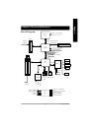
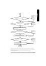
Страница 55 из 97 Block Diagram Pentium 4 CPU English Chapter 4 Technical Reference CPUCLK+/- (100/133MHz) AGP 4X System Bus 400/533MHzHz AGPCLK (66MHz) 100/133 MHz DDR RAM Intel 82845E HCLK+/- (100/133MHz) MCHCLK (66MHz) 66 MHz 33 MHz 14.318 MHz 48 MHz 5 PCI Game Port Floppy LPC BUS ITE8712 AC97 Link Intel ICH 4
Страница 56 из 97 English @ BIOS Introduction Gigabyte announces @ BIOS Windows BIOS live update utility Have you ever updated BIOS by yourself? Or like many other people, you just know what BIOS is, but always hesitate to update it? Because you think updating newest BIOS is unnecessary and actually you don’know how
Страница 57 из 97 English Easy TuneTM 4 Introduction Gigabyte announces EasyTuneTM 4 Windows based Overclocking utility EasyTune 4 carries on the heritage so as to pave the way for future generations. Overclock" might be one of the most common issues in computer field. But have many users ever tried it? The answer
Страница 58 из 97 English BIOS Flash Procedureyte @BIOS TM Program to flash BIOS. Method 1: We use GA-7VTX motherboard and Flash841 BIOS flash utility as example. Please flash the BIOS according to the following procedures if you are now under the DOS mode. Flash BIOS Procedure: STEP 1: (1) Please make sure your
Страница 59 из 97 and "Copy system files", after that press "Start". That will format the floppy and transfer the needed system files to it. Beware: This procedure will erase all the prior data on that floppy, so please proceed accordingly. (3) After the floppy has been formatted completely, please press "Close". -
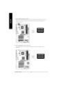
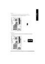
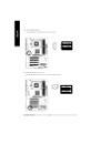
Страница 60 из 97 English STEP 3: Download BIOS and BIOS utility program. (1) Please go to Gigabyte website http://www.gigabyte.com.tw/index.html, and click "Support". (2) From Support zone, click the "Motherboards BIOS & Drivers". GA-8IE800 Motherboard - 56 -
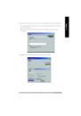
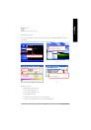
Страница 61 из 97 optional menu to obtain BIOS flash files. (4) Select an appropriate BIOS version (For example: F4), and click to download the file. It will pop up a file download screen, then select the "Open this file from its current location" and press "OK". - 57 - Technical Reference English (3) We use GA-7VTX
Страница 62 из 97 English (5) At this time the screen shows the following picture, please click "Extract" button to unzip the files. (6) Please extract the download files into the clean bootable floppy disk A mentioned in STEP 2, and press "Extract". GA-8IE800 Motherboard - 58 -
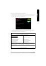
Страница 63 из 97 (1) Insert the floppy disk (contains bootable program and unzip file) into the floppy drive A. Then, restart the system. The system will boot from the floppy disk. Please press <DEL> key to enter BIOS setup main menu when system is boot up. Amer ican R el ea se :0 9/16 /9 9 Meg atre nd s AMIBIOS (C
Страница 64 из 97 English (3) Press "Enter" to enter "BIOS FEATURES SETUP" menu. Use the arrows to highlight the item "1st Boot Device", and then use the "Page Up" or "Page Down" keys to select "Floppy". AMIBIOS SETUP - BIOS FEATURES SETUP ( C ) 2001 American Megatrends, Inc. All Rights Reserved 1st Boot Device :
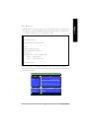
Страница 65 из 97 (1) After the system boot from floppy disk, type "A:\> dir/w" and press "Enter" to check the entire files in floppy A. Then type the "BIOS flash utility" and "BIOS file" after A:\>. In this case you have to type "A:\> Flash841 7VTX.F4" and then press "Enter". Starting Windows 98… Microsoft(R)
Страница 66 из 97 English (3) It will pop up a screen and asks "Are you sure to flash the BIOS?" Press [Enter] to continue theprocedure, or press [ESC] to quit. Beware: Please do not turn off the system while you are upgrading BIOS. It will render your BIOS corrupted and system totally inoperative. Are you sure to
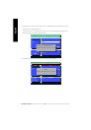
Страница 67 из 97 Normally the system redetects all devices after BIOS has been upgraded. Therefore, we highly recommend reloading the BIOS defaults after BIOS has been upgraded. This important step resets everything after the flash. (1) Take out the floppy diskette from floppy drive, and then restart the system.
Страница 68 из 97 English (3) Use the arrows to highlight the item "SAVE & EXIT SETUP" and press "Enter". System will ask "SAVE to CMOS and EXIT (Y/N)?" Press "Y" and "Enter" keys to confirm. Now the system will reboot automatically, the new BIOS setting will be taken effect next boot-up. AMIBIOS SIMPLE SETUP
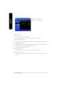
Страница 69 из 97 English Method 2: Q-Flash Introduction A. What is Q-Flash Utility? Q-Flash utility is a pre-O.S. BIOS flash utility enables users to update its BIOS within BIOS mode, no more fooling around any OS. B. How to use Q-Flash? a. After power on the computer, pressing <Del> immediately during POST (Power
Страница 70 из 97 English Load BIOS From Floppy !In the A:drive, insert the "BIOS" diskette, then Press Enter to Run. 1 File(s) found XXXX.XX 256K Total Size: 1.39M F5: Refresh Free Size: 1.14M DEL: Delete ESC: Return Main Where XXXX.XX is name of the BIOS file. !Press Enter to Run. Are you sure to update BIOS?
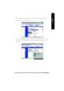
Страница 71 из 97 English Method 3: BIOS Flash Procedure BIOS update procedure: If you don’have DOS boot disk, we recommend that you used Gigabyte @BIOSTM Program to t flash BIOS. Follow the setup that showing on the scween to install the Utility. 2.Click"Start"-"Programs"Press here. "GIGABYTE"-"@BIOS" 1.Click
Страница 72 из 97 English II. Update BIOS NOT through Internet: a. b. c. d. Do not click "Internet Update" icon Click "Update New BIOS" Please select "All Files" in dialog box while opening the old file. Please search for BIOS unzip file, downloading from internet or any other methods (such as: 8IE800.F1). e.
Страница 73 из 97 The installation of windows 98SE/2K/ME/XP is very simple. Please follow next step to install the function! Stereo Speakers Connection and Settings: We recommend that you use the speaker with amplifier to acqiire the best sound effect if the stereo output is applied. STEP 1: Connect the stereo
Страница 74 из 97 English 4 Channel Analog Audio Output Mode STEP 1 : Connect the front channels to “Line Out”,the rear channels to “Line In”. Line Out Line In STEP 2 : After installation of the audio driver, you’ find an ll icon on the taskbar’ status area. Click the audio icon s “ Sound Effect”from the windows
Страница 75 из 97 English Basic 6 Channel Analog Audio Output Mode Use the back audio panel to connect the audio output without any additional module. STEP 1 : Line Out Connect the front channels to “ Out” rear chanLine ,the nels to “ Line In” and the Center/Subwoofer channels , to “ In ” MIC . Line In MIC In STEP 2
Страница 76 из 97 English Advanced 6 Channel Analog Audio Output Mode (using Audio Combo Kit,Optional Device): (Audio Combo Kit provides SPDIF output port : optical & coaxis and SURROUND-KIT : Rear R/L & CEN / Subwoofer) SURROUND-KIT access analog output to rear channels and Center/Subwoofer channels. It is the best
Страница 77 из 97 English STEP 3 : Connect the front channels to back audio panel’ s “ Line Out” the rear channels to SURROUND-KIT’ , s REAR R/L, and the Center/Subwoofer channels to SURROUND-KIT’ SUB CENTER. s STEP 4 : Click the audio icon “ Sound Effect”from the windows tray at the bottom of the screen. STEP 5 :
Страница 78 из 97 English SPDIF Output Device (Optional Device) A “SPDIF output” device is available on the motherboard. Cable with rear bracket is provided and could link to the “ SPDIF output”connector (As picture.) For the further linkage to decoder, rear bracket provides coaxialcable and Fiber connecting port.
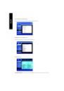
Страница 79 из 97 English Revision 5 Appendix Chapter History Install Drivers Picture below are shown in Windows XP (IUCD ver 2.22) Insert the driver CD-title that came with your motherboard into your CD-ROM drive, the driver CD-title will auto start and show the installation guide. If not, please double click the
Страница 80 из 97 English Driver install finished ! You have to reboot system ! Item Description n Intel Chipset Software Installation Utility Tell the operating system how the chipset components will be configured n Intel Application Accelerator Designed to improve performance of the storage sub-system and overall
Страница 81 из 97 This page reveals the value-added software developed by Gigabyte and its worldwide partners. n Gigabyte Windows Utilities Manager(GWUM) This utility can integrate the Gigabyte's applications in the system tray n Gigabyte Management Tool(GMT) A useful tool which can manage the computer via the
Страница 82 из 97 English SOFTWARE INFORMATION This page list the contects of softwares and drivers in this CD title. HARDWARE INFORMATION This page lists all device you have for this motherboard. CONTACT US GA-8IE800 Motherboard - 78 -
Страница 83 из 97 Below is a collection of general asked questions. To check general asked questions based on a specific motherboard model, please log on to http://tw.giga-byte.com/faq/faq.htm. Question 1: I cannot see some options that were included in previous BIOS after updating BIOS. Why? Answer: Some advanced
Страница 84 из 97 English Question 5: How do I clear CMOS? Answer: If your board has a Clear CMOS jumper, please refer to the Clear CMOS steps in the manual. If your board doesn¡¦ have such jumper, you can take off the on-board battery to leak t voltage to clear CMOS. Please refer to the steps below: Steps: 1. Turn
Страница 85 из 97 gAMI BIOS Beep Codes *Computer gives 1 short beep when system boots successfully. *Except for beep code 8, these codes are always fatal. 1 beep Refresh failure 2 beeps Parity error 3 beeps Base 64K memory failure 4 beeps Timer not operational 5 beeps Processor error 6 beeps 8042 - gate A20 failure
Страница 86 из 97 English Troubleshooting If you encounter any trouble during boot up, please follow the troubleshooting procedures . START Turn off the power and unplug theAC power cable, then remove all of the add-on cards and cables from motherboard. Please make sure motherboard & chassis are not short ? Yes
Страница 87 из 97 Is memory LED on and CPU fan running? No The problem could be caused by power supply, CPU, memory or CPU/ memory socket itself. Yes Failure hasbeen excluded. No Check if there is display. Yes Perhaps your VGA card / VG A slot or monitor is defectiv e. Failure hasbeen excluded. Turn off the system.
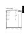
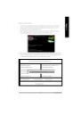
Страница 88 из 97 Customer/Country: Contact Person: Phone No.: E-mail Add. : Model name/Lot Number: BIOS version: Hardware Configuration CPU Company: & English Technical Support/RMA Sheet Mfs. PCB revision: O.S./A.S.: Modelname Size: Driver/Utility: Memory Brand Video Card Audio Card HDD CD-ROM / DVD-ROM Modem
Страница 89 из 97 Acronyms ACPI APM AGP Meaning Advanced Configuration and Power Interface Advanced Power Management Accelerated Graphics Port AMR ACR BIOS CPU CMOS CRIMM CNR DMA Audio Modem Riser Advanced Communications Riser Basic Input / Output System Central Processing Unit Complementary Metal Oxide
Страница 90 из 97 English Acronyms Meaning IOAPIC ISA LAN I/O LBA LED MHz MIDI Input Output Advanced Programmable Input Controller Industry Standard Architecture Local Area Network Input / Output Logical Block Addressing Light Emitting Diode Megahertz Musical Instrument Digital Interface MTH MPT NIC OS OEM PAC POST
Страница 96 из 97 English CONTACT US Contact us via the information in this page all over the world. — Taiwan — U.K Gigabyte Technology Co., Ltd. Address: No.6, Bau Chiang Road, Hsin-Tien, Taipei Hsien, Taiwan, R.O.C. TEL: 886 (2) 8912-4888 (50 lines) FAX: 886 (2) 8912-4004 Technical issue: