Доступность: Бесплатно как и все руководства на сайте. Без регистрации и SMS.
Дополнительно: Чтение инструкции онлайн
USER’S MANUAL
GA-8ILMT4
P4 Titan-DDR Motherboard
Pentium
®
4 Processor Motherboard
Rev. 1001
12ME-8ILMT4-1001
Страница: (4 из 82)
навигация
1
2
3
4
5
6
7
8
9
10
11
12
13
14
15
16
17
18
19
20
21
22
23
24
25
26
27
28
29
30
31
32
33
34
35
36
37
38
39
40
41
42
43
44
45
46
47
48
49
50
51
52
53
54
55
56
57
58
59
60
61
62
63
64
65
66
67
68
69
70
71
72
73
74
75
76
77
78
79
80
81
82
Оглавление инструкции
Страница 1 из 83 ! The author assumes no responsibility for any errors or omissions that may appear in this document nor does the author make a commitment to up date the information contained herein. ! Third-party brands and names are the property of their respective owners. ! Please do not remove any labels on
Страница 2 из 83 Declaration of Conformity We, Manufacturer/Importer (full address) G.B.T. Technology Träding GMbH Ausschlager Weg 41, 1F, 20537 Hamburg, Germany declare that the product ( description of the apparatus, system, installation to which it refers) Mother Board GA-8ILMT4 is in conformity with (reference
Страница 3 из 83 DECLARATION OF CONFORMITY Per FCC Part 2 Section 2.1077(a) Responsible Party Name: G.B.T. INC. (U.S.A.) Address: 17358 Railroad Street City of Industry, CA 91748 Phone/Fax No: (818) 854-9338/ (818) 854-9339 hereby declares that the product Product Name: Motherboard Model Number:GA-8ILMT4 Conforms
Страница 5 из 83 English Table of Content Item Checklist ......................................................................................... 4 WARNING! ............................................................................................... 4 Chapter 1 Introduction
Страница 6 из 83 PC Health Status........................................................................................ 39 Frequency/Voltage Control ........................................................................ 41 Top Performance
Страница 7 из 83 English Item Checklist ! The GA-8ILMT4 motherboard ! IDE cable x 1/ Floppy cable x 1 ! I/O Shield ! CD for motherboard driver & utility (IUCD) ! GA-8ILMT4 user’s manual WARNING! Computer motherboards and expansion cards contain very delicate Integrated Circuit (IC) chips. To protect them against
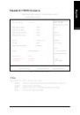
Страница 8 из 83 Features Summary Form Factor ! 21.0cm x 24.3cm Micro ATX size form factor, 4 layers PCB. CPU ! Socket 478 for Intel® Micro FC-PGA2 Pentium® 4 processor ! Support Intel® Pentium® 4 (Northwood, 0.13 m) processor ! ! Intel Pentium®4 400MHz FSB 2nd cache depends on CPU Chipset ! ! Chipset 82845GL
Страница 9 из 83 English Hardware Monitor ! ! CPU/System Fan Revolution detect CPU/System Fan Control ! ! CPU Overheat Warning System Voltage Detect PS/2 Connector BIOS ! ! PS/2 Keyboard interface and PS/2 Mouse interace Licensed AWARD BIOS, 2M bit FWH Additional Features ! ! External Modem wake up PS/2 Keyboard
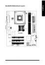
Страница 10 из 83 KB_MS COMA ATX_POWER FDD CPU_FAN DIMM_LED LPT VGA DDR2 DDR1 English GA-8ILMT4 Motherboard Layout ATX_12V IDE1 IDE2 GA-8ILMT4 BAT1 PCI1 ICH4 Buzzer CLR_COMS SYS _FAN ITE8712 RTL8100BL PCI2 CI AUX_IN AC97 F_USB2 BIOS_WP GAME F_AUDIO Intel 845GL USB/ LAN MIC_IN LINE_OUT LINE_IN SOCKET478 BIOS PCI3
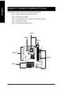
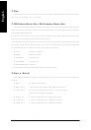
Страница 11 из 83 English Chapter 2 Hardware Installation Process To set up your computer, you must complete the following steps: Step 1- Install the Central Processing Unit (CPU) Step 2- Install memory modules Step 3- Connect ribbon cables, cabinet wires, and power supply Step 4- Setup BIOS software Step 5- Install
Страница 12 из 83 Step 1-1 : CPU Installation Pin1 indicator Pin1 indicator CPU Top View CPU Bottom View Socket Actuation Lever 1. Pull up the CPU socket lever and up to 90-degree angle. Pin1 indicator 2. Locate Pin 1 in the socket and look for a (golden) cut edge on the CPU upper corner. Then insert the CPU into
Страница 13 из 83 English Step 1-2 : CPU Heat Sink Installation 2. Hook the other end of the 1. Hook one end of the cooler cooler bracket to the CPU socket. bracket to the CPU socket first. # Please use Intel approved cooling fan. # We recommend you to apply the thermal tape to provide better heat conduction between
Страница 14 из 83 The motherboard has 2 dual inline memory module (DIMM) sockets. The BIOS will automatically detects memory type and size. To install the memory module, just push it vertically into the DIMM Slot .The DIMM module can only fit in one direction due to the notch. Memory size can vary between sockets.
Страница 15 из 83 English DDR Introduction Established on the existing SDRAM industry infrastructure, DDR (Double Data Rate) memory is a high performance and cost-effective solution that allows easy adoption for memory vendors, OEMs and system integrators. DDR memory is a sensible evolutionary solution for the PC
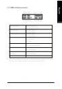
Страница 16 из 83 Step3-1 : I/O Back Panel Introduction # " $ & % " PS/2 Keyboard and PS/2 Mouse Connector PS/2 Mouse Connector (6 pin Female) $This connector supports standard PS/2 keyboard and PS/2 mouse. PS/2 Keyboard Connector (6 pin Female) # Parallel Port and Serial Ports (COM1/COM2) Parallel Port (25 pin
Страница 17 из 83 English $ Game /MIDI Ports $This connector supports joystick, MIDI keyboard and other relate audio devices. Joystick/ MIDI (15 pin Female) % Audio Connectors $ After install onboard audio driver, you may connect speaker to Line Out jack, micro phone to MIC In jack. Device like CD-ROM , walkman etc
Страница 18 из 83 A English Step 3-2 : Connectors Introduction C B D E R F G Q H P I O A) B) C) D) E) F) G) H) I) N M L ATX_12V CPU_FAN ATX FDD IDE1/IDE2 SYS_FAN CLR_CMOS BIOS_WP CI K J) K) L) M) N) O) P) Q) R) - 15 - J F_PANEL PWR_LED F_USB1/F_USB2 BATTERY COMB CD_IN IR AUX_IN F_AUDIO Hardware Installation Process
Страница 19 из 83 $ This connector (ATX +12V) suppliesthe CPU operation voltage (Vcore). If this " ATX+ 12V connector" is not connected, system cannot 3 4 boot. +12V GND +12V GND 1 2 B) CPU_FAN (CPU FAN Connector) $ Please note, a proper installation of the CPU cooler is essential to prevent the CPU from running
Страница 20 из 83 $ Important Notice: Please connect first harddisk to IDE1 and connect CDROM to IDE2. 1 IDE1 IDE2 1 F) SYS_FAN (System FAN Connector) Sense +12V/Control GND 1 G) CLR_CMOS (Clear CMOS) 2-3 close: Normal 1 $ You may clear the CMOS data to its default values by this jumper. Default doesn’t include the
Страница 21 из 83 BIOS_WP must be set to 2-3 close. We recommend BIOS_WP to be set to "1-2 close", 2-3 close: Normal 1 whenever user does not need to flash/upgrade the BIOS. 1-2 close: Write Protection 1 I) CI (CASE OPEN) $ This 2 pin connector allows your system to enable or disable the system alarm if the sys tem
Страница 22 из 83 CAUTION % Danger of explosion if battery is incorrectly replaced. % Replace only with the same or equivalent type recommended by the manufacturer. + % Dispose of used batteries according to the manufacturer’s instructions. NSINB NDTRBNDSRBNCTSBNC N) COM B NDCDBNSOUTB GND NRTSBNRIB- 1 O) CD_IN (CD
Страница 23 из 83 $ Be careful with the polarity of the IR IR Data Input GND IR Data Output VCC(+5V) connectorwhile you connect the IR. Please contact you nearest dealer for optional IR device. 1 Q) AUX_IN ( AUX In Connector) 1 AUX-L GND AUX-R English P)IR R)F_AUDIO (F_AUDIO Connector) $ If you want to use Front
Страница 24 из 83 SPK- 1 SPK+ 20 GD+ 1 GDGN+ 1 GN- NC 1 MPD+ MPD- 1 PW+ PWRSTRST+ 1 1 HD+ 1 HD- 2 GN (Green Switch) 19 Open: Normal Operation GD (Green LED) English J) F_PANEL (2x10 pins connector) Close: Entering Green Mode Pin 1: LED anode(+) Pin 2: LED cathode(-) HD (IDE Hard Disk Active LED) Pin 1: LED anode(+)
Страница 25 из 83 English Chapter 3 BIOS Setup BIOS Setup is an overview of the BIOS Setup Program. The program that allows users to modify the basic system configuration. This type of information is stored in battery-backed CMOS RAM so that it retains the Setup information when the power is turned off. ENTERING
Страница 26 из 83 Main Menu The on-line description of the highlighted setup function is displayed at the bottom of the screen. Status Page Setup Menu / Option Page Setup Menu Press F1 to pop up a small help window that describes the appropriate keys to use and the possible selections for the highlighted item. To
Страница 27 из 83 English % Integrated Peripherals This setup page includes all onboard peripherals. % Power Management Setup This setup page includes all the items of Green function features. % PnP/PCI Configurations This setup page includes all the configurations of PCI & PnP ISA resources. % PC Health Status This
Страница 28 из 83 English Standard CMOS Features CMOS Setup Utility-Copyright (C) 1984-2002 Award Software Standard CMOS Features Date (mm:dd:yy) Mon, Feb 21 2000 Time (hh:mm:ss) 22:31:24 Item Help Menu Level & Change the day, month, !IDE Primary Master None ! IDE Primary Slave None year !IDE Secondary Master None
Страница 29 из 83 English ! Time The times format in <hour> <minute> <second>. The time is calculated base on the 24-hour militarytime clock. For example, 1 p.m. is 13:00:00. ! IDE Primary Master, Slave / IDE Secondary Master, Slave The category identifies the types of hard disk from drive C to F that has been
Страница 30 из 83 !Disabled Normal Floppy Drive. (Default value) !Drive A Drive A is 3 mode Floppy Drive. !Drive B Drive B is 3 mode Floppy Drive. !Both English ! Floppy 3 Mode Support (for Japan Area) Drive A & B are 3 mode Floppy Drives. !Halt on The category determines whether the computer will stop if an error
Страница 31 из 83 English Advanced BIOS Features CMOS Setup Utility-Copyright (C) 1984-2002 Award Software Advanced BIOS Features First Boot Device Floppy Item Help Second Boot Device HDD-0 Menu Level & Third Boot Device CDROM Boot Up Floppy Seek Disabled Init Display First Onboard/AGP Graphics Aperture Size 128MB
Страница 32 из 83 During POST, BIOS will determine the floppy disk drive installed is 40 or 80 tracks. 360 K type is 40 tracks 720 K, 1.2 M and 1.44 M are all 80 tracks. !Enabled BIOS searches for floppy disk drive to determine it is 40 or 80 tracks. Note that BIOS can not tell from 720 K, 1.2 M or 1.44 M drive type
Страница 33 из 83 English Integrated Peripherals CMOS Setup Utility-Copyright (C) 1984-2002 Award Software Integrated Peripherals On-Chip Primary PCI IDE Enabled Item Help Menu Level & On-Chip Secondary PCI IDE Enabled IDE1 Conductor Cable Auto If a hard disk IDE2 Conductor Cable Auto controller card is USB
Страница 34 из 83 !Enabled Enable onboard 2nd channel IDE port. (Default value) !Disabled English ! On-Chip Secondary PCI IDE Disable onboard 2nd channel IDE port. ! IDE1 Conductor Cable !Auto Will be automatically detected by BIOS. (Default Value) !ATA66/100 Set IDE1 Conductor Cable to ATA66/100 (Please make sure
Страница 35 из 83 English ! AC97 Audio !Auto Enable onboard AC'97 audio function. (Default Value) !Disabled Disable this function. ! Onboard LAN !Enabled Enabled Onboard LAN function. (Default value) !Disabled Disabled onboard LAN function. ! Onboard LAN Boot ROM !Enabled Enabled Onboard LAN Boot ROM function.
Страница 36 из 83 !Half IR Function Duplex Half. (Default Value) !Full English ! UR2 Duplex Mode IR Function Duplex Full. ! Onboard Serial Port 2 !Auto BIOS will automatically setup the port 2 address. !3F8/IRQ4 Enable onboard Serial port 2 and address is 3F8. !2F8/IRQ3 Enable onboard Serial port 2 and address is
Страница 37 из 83 English !ECP Mode Use DMA !3 Set ECP Mode Use DMA to 3. (Default Value) !1 Set ECP Mode Use DMA to 1. !Game Port Address !201 Set Game Port Address to 201. (Default Value) !209 Set Game Port Address to 209. !Disabled Disable this function. !Midi Port Address !300 Set Midi Port Address to 300. !330
Страница 38 из 83 English Power Management Setup CMOS Setup Utility-Copyright (C) 1984-2002 Award Software Power Management Setup ACPI Suspend Type S1(POS) Item Help Soft-Off by PWR_BTTN Instant-Off Menu Level & PME Event Wake Up Enabled [S1] ModemRingOn/WakeOnLan Enabled Resume by Alarm Disabled Set suspend type to
Страница 39 из 83 English ! Soft-off by PWR_BTTN !Instant-off Press power button then Power off instantly. (Default value) !Delay 4 Sec. Press power button 4 sec to Power off. Enter suspend if button is pressed less than 4 sec. ! PME Event Wake Up !Disabled Disable this function. !Enabled Enable PME Event Wake up.
Страница 40 из 83 !Enter Input password (from 1 to 5 characters) and press Enter to set the Key board Power On Password. !AC Back Function !Memory System power on depends on the status before AC lost. !Soft-Off Always in Off state when AC back. (Default value) !Full-On Always power on the system when AC back. - 37 -
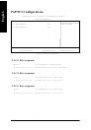
Страница 41 из 83 English PnP/PCI Configurations CMOS Setup Utility-Copyright (C) 1984-2002 Award Software PnP/PCI Configurations PCI 1 IRQ Assignment Auto Item Help PCI 2 IRQ Assignment Auto Menu Level & PCI 3 IRQ Assignment Auto "#$%: Move Enter:Select +/-/PU/PD:Value F10:Save ESC:Exit F5:Previous Values
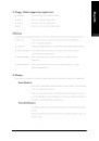
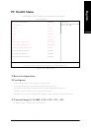
Страница 42 из 83 English PC Health Status CMOS Setup Utility-Copyright (C) 1984-2002 Award Software PC Health Status Reset Case Open Status Disabled Item Help Menu Level & Case Opened No VCORE 1.730V +1.5V 1.502V +3.3V 3.360V +5V 5.053V +12V 11.840V Current CPU Temperature 35°C/95°F Current CPU FAN Speed 6490 RPM
Страница 43 из 83 English !Current CPU Temperature !Detect CPU Temp. automatically. ! Current CPU/SYSTEM FAN Speed (RPM) !Detect CPU/SYSTEM Fan speed status automatically. ! CPU Warning Temperature !60°C / 140°F Monitor CPU Temp. at 60°C / 140°F. !70°C / 158°F Monitor CPU Temp. at 70°C / 158°F. !80°C / 176°F Monitor
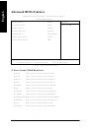
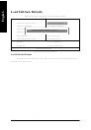
Страница 44 из 83 English Frequency/Voltage Control CMOS Setup Utility-Copyright (C) 1984-2002 Award Software Frequency/Voltage Control CPU Clock Ratio 15X Item Help CPU Host Clock Control Disabled Menu Level & x CPU Host Frequency (Mhz) 100 x PCI/AGP Divider Disabled Host/DRAM Clock ratio Auto Memory Frequency
Страница 45 из 83 English !PCI/AGP Divider !You can choose Disabled,PLL/40,PLL/32,PLL/24,PLL/20/PLL/16 mode to adjust PCI/AGP frequency. !Host/DRAM Clock Ratio (Warning: wrong frequency may make system can’t boot, clear CMOS to overcome wrong fre quency issue) !2.0 Memory Frequency = Host clock X 2.0. !2.66 Memory
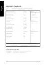
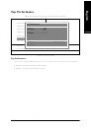
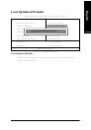
Страница 46 из 83 English Top Performance CMOS Setup Utility-Copyright (C) 1984-2002 Award Software !Standard CMOS Features Load Fail-Safe Defaults !Advanced BIOS Features Load Optimized Defaults !Integrated Peripherals Set Supervisor Password Top Performance !Power Management Setup Disabled...................[ &]
Страница 47 из 83 English Load Fail-Safe Defaults CMOS Setup Utility-Copyright (C) 1984-2002 Award Software !Standard CMOS Features Top Performance ! Advanced Chipset Features Load Fail-Safe Defaults !Integrated Peripherals Load Optimized Defaults !Power Management Setup Set Supervisor Password !PnP/PCI
Страница 48 из 83 English Load Optimized Defaults CMOS Setup Utility-Copyright (C) 1984-2002 Award Software !Standard CMOS Features Top Performance !Advanced BIOS Features Load Fail-Safe Defaults !Integrated Peripherals Load Optimized Defaults !Power Management Setup Set Supervisor Password Load Optimized
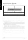
Страница 49 из 83 English Set Supervisor/User Password CMOS Setup Utility-Copyright (C) 1984-2002 Award Software !Standard CMOS Features Top Performance !Advanced BIOS Features Load Fail-Safe Defaults !Integrated Peripherals Load Optimized Defaults !Power Management Setup Set Supervisor Password !PnP/PCI
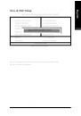
Страница 50 из 83 English Save & Exit Setup CMOS Setup Utility-Copyright (C) 1984-2002 Award Software !Standard CMOS Features Top Performance !Advanced BIOS Features Load Fail-Safe Defaults !Integrated Peripherals Load Optimized Defaults !Power Management Setup Set Supervisor Password !PnP/PCI Configurations Set
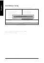
Страница 51 из 83 English Exit Without Saving CMOS Setup Utility-Copyright (C) 1984-2002 Award Software !Standard CMOS Features Top Performance !Advanced BIOS Features Load Fail-Safe Defaults !Integrated Peripherals Load Optimized Defaults !Power Management Setup Set Supervisor Password !PnP/PCI Configurations Set
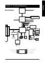
Страница 52 из 83 Block Diagram Pentium 4 CPU English Revision History Chapter 4 Technical Reference CPUCLK± (100/133MHz) System Bus 400MHz 200/266 MHz DDR RAM AGPCLK (66MHz) Intel 82845GL HCLK± (100/133MHz) GMCHCLK (66MHz) 66 MHz 33 MHz 14.318 MHz 48 MHz 3 PCI FWH Intel ICH 4 Game Port LPC BUS Floppy ITE8712 LPT
Страница 53 из 83 English Q-Flash Introduction A. What is Q-Flash Utility? Q-Flash utility is a pre-O.S. BIOS flash utility enables users to update its BIOS within BIOS mode, no more fooling around any OS. B. How to use Q-Flash? a. After power on the computer, pressing <Del> immediately during POST (Power On Self
Страница 54 из 83 !In the A:drive, insert the "BIOS" diskette, then Press Enter to Run. 1 File(s) found XXXX.XX Total Size: 1.39M F5: Refresh 256K DEL: Delete Free Size: 1.14M ESC: Return Main Where XXXX.XX is name of the BIOS file. !Press Enter to Run. Are you sure to update BIOS? [Enter] to contiune Or [ESC] ot
Страница 55 из 83 English @ BIOS Introduction Gigabyte announces @ BIOS Windows BIOS live update utility Have you ever updated BIOS by yourself? Or like many other people, you just know what BIOS is, but always hesitate to update it? Because you think updating newest BIOS is unnecessary and actually you don’t know
Страница 56 из 83 English Easy TuneTM 4 Introduction Gigabyte announces EasyTuneTM 4 Windows based Overclocking utility EasyTune 4 carries on the heritage so as to pave the way for future generations. Overclock" might be one of the most common issues in computer field. But have many users ever tried it? The answer
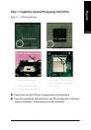
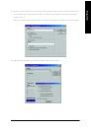
Страница 57 из 83 English Revision History Chapter 5 Appendix Picture below are shown in Windows XP (IUCD driver version 2.0) Insert the driver CD-title that came with your motherboard into your CD-ROM driver, the driver CD-title will auto start and show the installation guide. If not, please double click the CD-ROM
Страница 58 из 83 Insert the driver CD-title that came with your motherboard into your CD-ROM driver, the driver CD-title will auto start and show the installation guide. If not, please double click the CD-ROM device icon in "My computer", and execute the setup.exe. 1.Click "Intel Chipset Software Installation
Страница 59 из 83 English 5.Click "Finish" to restart computer. (5) GA-8ILMT4 Motherboard (6) - 56 -
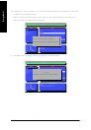
Страница 60 из 83 Insert the driver CD-title that came with your motherboard into your CD-ROM driver, the driver CD-title will auto start and show the installation guide. If not, please double click the CD-ROM device icon in "My computer", and execute the setup.exe. 1.Click "Intel Application Accelerator" item. (2)
Страница 61 из 83 English 6.Click "Finish" to restart computer. (7) GA-8ILMT4 Motherboard (8) - 58 -
Страница 62 из 83 Insert the driver CD-title that came with your motherboard into your CD-ROM driver, the driver CD-title will auto start and show the installation guide. If not, please double click the CD-ROM device icon in "My computer", and execute the setup.exe. 1.Click "Intel 845G Chipset VGA Graphics Driver"
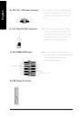
Страница 63 из 83 English 4.Click "Finish" to restart computer. (5) A-4. USB Patch Driver Insert the driver CD-title that came with your motherboard into your CD-ROM driver, the driver CD-title will auto start and show the installation guide. If not, please double click the CD-ROM device icon in "My computer", and
Страница 64 из 83 Insert the driver CD-title that came with your motherboard into your CD-ROM driver, the driver CD-title will auto start and show the installation guide. If not, please double click the CD-ROM device icon in "My computer", and execute the setup.exe. Revision History 1.Click "Sigmatel AC’97 Audio
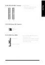
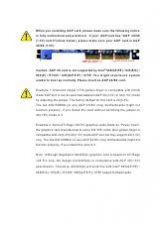
Страница 65 из 83 English Appendix C: RealTek 8139/8130/8100 Network Driver For your reference, you can use the following steps to complete the RealTek 8139/8130/8100 Network Driver Installation. 1.Click "RealTek Network Driver" item. (2) (1) 2.Click "Finish" to restart computer. (4) (3) GA-8ILMT4 Motherboard - 62 -
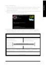
Страница 66 из 83 Insert the driver CD-title that came with your motherboard into your CD-ROM driver, the driver CD-title will auto start and show the installation guide. If not, please double click the CD-ROM device icon in "My computer", and execute the setup.exe. Press "Tools" icon. 2.Click "Easy Tune 4". 1.Click
Страница 67 из 83 English Appendix E: BIOS Flash Procedure BIOS update procedure: Method 1: If your OS is Win9X, we recommend that you used Gigabyte @BIOSTM Program to flash BIOS. 2.Click "@BIOS Writer Utility Press "Tools" icon. v.1.08q". 1.Click "Gigabyte Utilities". (2) (1) Click " ". Click here. (3) Methods and
Страница 68 из 83 English II. Update BIOS NOT through Internet: a. Do not click "Internet Update" icon b. Click "Update New BIOS" c. Please select "All Files" in dialog box while opening the old file. d. Please search for BIOS unzip file, downloading from internet or any other methods (such as: 8ILMT4.F1). e.
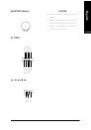
Страница 69 из 83 English Method 2: We use GA-7VTX motherboard and Flash841 BIOS flash utility as example. Please flash the BIOS according to the following procedures if you are now under the DOS mode. Flash BIOS Procedure: STEP 1: (1) Please make sure your system has installed the extraction utility such as winzip
Страница 70 из 83 system files to it. Beware: This procedure will erase all the prior data on that floppy, so please proceed accordingly. (3) After the floppy has been formatted completely, please press "Close". - 67 - Appendix English (2) Select the "Quick (erase)" for Format Type, and pick both "Display summary
Страница 71 из 83 English STEP 3: Download BIOS and BIOS utility program. (1) Please go to Gigabyte website http://www.gigabyte.com.tw/index.html, and click "Support". (2) From Support zone, click the "Motherboards BIOS & Drivers". GA-8ILMT4 Motherboard - 68 -
Страница 72 из 83 (4) Select an appropriate BIOS version (For example: F4), and click to download the file. It will pop up a file download screen, then select the "Open this file from its current location" and press "OK". - 69 - Appendix English (3) We use GA-7VTX motherboard as example. Please select GA-7VTX by
Страница 73 из 83 English (5) At this time the screen shows the following picture, please click "Extract" button to unzip the files. (6) Please extract the download files into the clean bootable floppy disk A mentioned in STEP 2, and press "Extract". GA-8ILMT4 Motherboard - 70 -
Страница 74 из 83 restart the system. The system will boot from the floppy disk. Please press <DEL> key to enter BIOS setup main menu when system is boot up. American Release:09/16/99 Megatrends AMIBIOS (C) 1999 American Megatrend 7VTX F1 Check System Health OK AMD-Athlon(tm)Processor-900MHz Checking NVRAM...
Страница 75 из 83 English (3) Press "Enter" to enter "BIOS FEATURES SETUP" menu. Use the arrows to highlight the item "1st Boot Device", and then use the "Page Up" or "Page Down" keys to select "Floppy". AMIBIOS SETUP - BIOS FEATURES SETUP ( C ) 2001 American Megatrends, Inc. All Rights Reserved 1st Boot Device :
Страница 77 из 83 English (3) It will pop up a screen and asks "Are you sure to flash the BIOS?" Press [Enter] to continue the procedure, or press [ESC] to quit. Beware: Please do not turn off the system while you are upgrading BIOS. It will render your BIOS corrupted and system totally inoperative. Are you sure to
Страница 78 из 83 recommend reloading the BIOS defaults after BIOS has been upgraded. This important step resets everything after the flash. (1) Take out the floppy diskette from floppy drive, and then restart the system. The boot up screen will indicate your motherboard model and current BIOS version. American
Страница 79 из 83 English (3) Use the arrows to highlight the item "SAVE & EXIT SETUP" and press "Enter". System will ask "SAVE to CMOS and EXIT (Y/N)?" Press "Y" and "Enter" keys to confirm. Now the system will reboot automatically, the new BIOS setting will be taken effect next boot-up. AMIBIOS SIMPLE SETUP
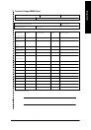
Страница 80 из 83 Acronyms ACPI Meaning Advanced Configuration and Power Interface APM AGP Advanced Power Management Accelerated Graphics Port AMR ACR Audio Modem Riser Advanced Communications Riser BIOS CPU Basic Input / Output System Central Processing Unit CMOS CRIMM Complementary Metal Oxide Semiconductor
Страница 81 из 83 English Acronyms LBA Meaning Logical Block Addressing LED MHz Light Emitting Diode Megahertz MIDI MTH Musical Interface Digital Interface Memory Translator Hub MPT NIC Memory Protocol Translator Network Interface Card OS OEM Operating System Original Equipment Manufacturer PAC POST PCI A.G.P.
Страница 82 из 83 Customer/Country: Company: Contact Person: O.S./A.S.: Hardware Model name Phone No.: E-mail Add. : Model name/Lot Number: BIOS version: English Technical Support/RMA Sheet Mfs. PCB revision: Size: Driver/Utility: Configuration CPU Memory Brand Video Card Audio Card HDD CD-ROM / DVD-ROM Modem