15
INSTALLATION INSTRUCTIONS
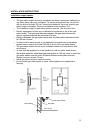
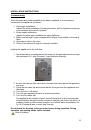
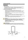
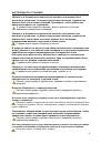
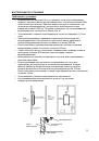
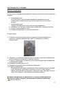
3. Installation of gas pipe
•
The size gas connector is G1/2 or G3/4, depends on the model.
•
The pipeline system should reach minimum rated gas pressure value for
the heater to perform the rated thermal load.
•
Before connecting up the appliance it is necessary to thoroughly flush and
purge the water and gas pipes in order to remove filings or other waste
from them.
•
Connect the gas transferring pipe to the relevant gas inlet nozzle and apply
clamp to tighten the hose. When pipeline gas is adopted, gas company
should apply corresponding hose where meter with flow value more than 3
m
3
/h is recommended.
•
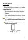
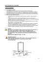
Purge air from the gas supply pipes.
•
Test gas circuit for tightness in accordance with current regulation.
Use appliance only with type of gas, stated on the marking plate!
The maximum inlet gas (G20) pressure must be limited to 18 mbar.
Minimum gas (G20) pressure must be higher than 10 mbar.
For Ukraine and Russian market 13 mbar nozzles are installed.
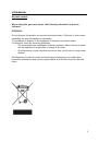
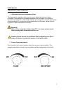
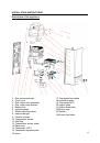
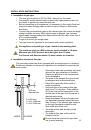
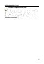
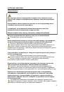
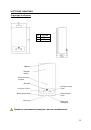
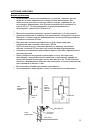
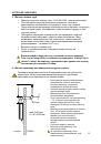
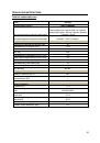
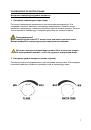
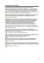
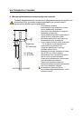
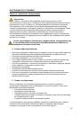
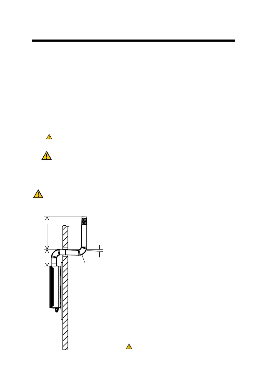
4. Installation of exhaust flue pipe
The gas water heater should be equipped with an exhaust pipe or a chimney.
Please pay attention to the specific regulations for installation required by the
local country.
•
Gas water heater can be started only when
exhaust flue pipe installation is finished.
Please pay attention to the requirements
for the installation.
•
The parts of the exhaust flue pipe should
be equipped with solid exhaust pipe.
•
Exhaust flue pipe should be made of
rustproof material.
•
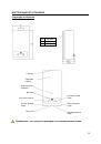
Horizontal part of the exhaust flue pipe
shall have 1% inclination. There shall be
Φ
=10 mm hole at the lowest point of the
vertical part of the pipe for the purpose of
draining water drops.
•
Distance between exhaust flue pipe and
any flammable materials should be more
than 150 mm. If the exhaust pipe needs to
go through flammable material or wall,
heat shield should be used.
•
The exhaust flue pipe should be fixed
thoroughly.
•
The exhaust flue pipe outlet must be
installed outside.
Do not touch the exhaust flue pipe after
use to avoid scalding.
A
≥
250 mm
A + B
≥
1800 mm
A + B
≤
2200 mm
B
A
1°
OUTSIDE
INSIDE
Φ
10 mm
draining hole