English
14
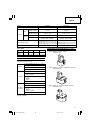
10. Using the hook
CAUTION
䡬
When using the hook, pay sufficient attention so
that the main equipment does not fall. If the tool
falls, there is a risk of accident.
䡬
Do not attach the tip tool except phillips bit to the
tool main unit when carrying the tool main unit with
the hook suspended from a waist belt.
Injury may result if you carry the equipment
suspended from the waist belt with sharp tipped
components such as drill bit attached.
The hook can be installed on the right or left side and
the angle can be adjusted in 5 steps between 0° and
80°.
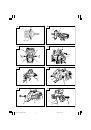
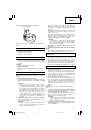
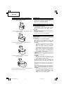
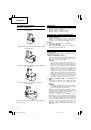
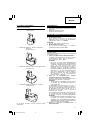
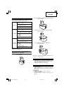
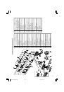
(1) Operating the hook
(a) Pull out the hook toward you in the direction
of arrow (A) and turn in the direction of arrow
(B) (
Fig. 12
).
(b) The angle can be adjusted in 5 steps (0°, 20°,
40°, 60°, 80°).
Adjust the angle of the hook to the desired
position for use.
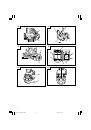
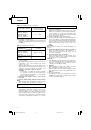
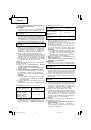
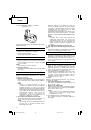
(2) Switching the hook position
CAUTION
Incomplete installation of the hook may result in
bodily injury when used.
(a) Securely hold the main unit and remove the
screw using a slotted head screwdriver or a coin
(
Fig. 13
).
(b) Remove the hook and spring (
Fig. 14
).
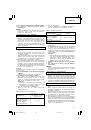
(c) Install the hook and spring on the other side and
securely fasten with screw (
Fig. 15
).
NOTE
Pay attention to the spring orientation. Install the
spring with larger diameter away from you (
Fig. 15
).
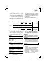
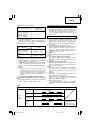
(3) Using the bit holder (Hook with bit holder)
䡬
Installing the bit
Slide the bit from the side and then insert firmly
until the groove on the bit locks in the protruded
section of the hook.
䡬
Removing the bit
Securely hold the main unit and pull out the bit
by holding the tip with your thumb (
Fig. 16
).
CAUTION
䡬
Only Hitachi STANDARD ACCESSORIES phillips bit
(No. 2
×
65L; Code No. 983006) may be used. Do
not use other bits since they may come loose.
(4) Using as an auxiliary light (Hook with light)
(a) Press the switch to turn off the light.
If forgotten, the light will turn off automatically
after 15 minutes.
(b) The direction of the light can be adjusted within
the range of hook positions 1 - 5 (
Fig. 17
).
䡬
Lighting time
AAAA manganese batteries: approx. 15 hrs.
AAAA alkali batteries: approx. 30 hrs.
CAUTION
Do not look directly into the light.
Such actions could result in eye injury.
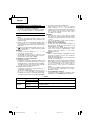
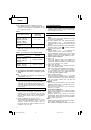
(5) Replacing the batteries
(a) Loosen the hook screw with a phillips-head
screwdriver (No. 1) (
Fig. 18
).
Remove the hook cover by pushing in the
direction of the arrow (
Fig. 19
).
CAUTION
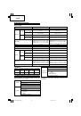
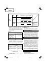
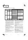
䡬
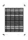
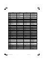
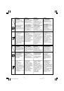
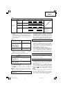
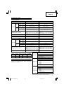
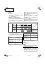
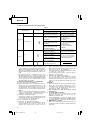
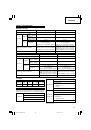
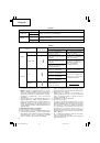
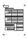
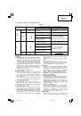
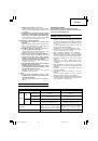
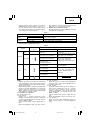
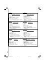
The selection examples shown in
Table 7
should
be considered as general standard. As different
types of tightening screws and different materials
to be tightened are used in actual works proper
adjustments are naturally necessary.
䡬
When using the driver drill with a machine screw
at HIGH (high speed), a screw may damage or a
bit may loose due to the tightning torque is too
strong. Use the driver drill at LOW (low speed)
when using a machine screw.
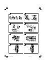
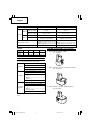
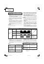
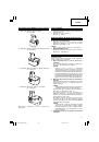
6. Mounting and dismounting of the bit
<For double sleeve chuck>
(1) After inserting a driver bit, etc. into the keyless drill
chuck, firmly grasp the ring and tighten the sleeve
by turning it toward the right (in the clockwise
direction as viewed from the front) (See
Fig. 9
).
䡬
If the sleeve becomes loose during operation, tighten
it further. The tightening force becomes stronger
when the sleeve is tightened additionally.
(2) Dismounting the bit
Firmly grasp the ring and loosen the sleeve by
turning it toward the left (in the counter-clockwise
direction as viewed from the front) (See
Fig. 9
).
<For single sleeve chuck>
(1) Mounting the bit
Loosen the sleeve by turning it toward the left (in
the counterclockwise direction as viewed from the
front) to open the clip on the keyless chuck. After
inserting a driver bit, etc., into the keyless drill
chuck, and tighten the sleeve by turning it toward
the right (in the clockwise direction as viewed from
the front) (See
Fig. 10
).
䡬
If the sleeve becomes loose during operation, tighten
it further.
The tightening force becomes stronger when the
sleeve is tightened additionally.
(2) Dismounting the bit
Loosen the sleeve by turning it toward the left (in
the counterclockwise direction as viewed from the
front), and then take out the bit, etc (See
Fig. 10
).
CAUTION
䡬
When it is no longer possible to loosen the sleeve,
use a vise or similar instrument to secure the bit. Set
the clutch mode between 1 and 11, and then turn
the sleeve to the loose side (left side) while operating
the clutch. It should be easy now to loosen the sleeve.
7. Confirm that the battery is mounted correctly
8. Check the rotational direction
The bit rotates clockwise (viewed from the rear
side) by pushing the R-side of the selector button.
The L-side of the selector button is pushed to turn
the bit counterclockwise (See
Fig. 11
) (The
L
and
R
marks are provided on the body).
9. Switch operation
䡬
When the trigger switch is depressed, the tool
rotates. When the trigger is released, the tool stops.
䡬
The rotational speed of the drill can be controlled by
varying the amount that the trigger switch is pulled.
Speed is low when the trigger switch is pulled slightly
and increases as the trigger switch is pulled more.
NOTE
䡬
A buzzing noise is produced when the motor is about
to rotate; This is only a noise, not a machine failure.
01Eng_DS9DVF3_EE
1/20/09, 16:00
14