9
English
PRACTICAL GRINDER APPLICATION
1. Pressure
To prolong the life of the machine and ensure a
first class finish, it is important that the machine
should not be overloaded by applying too much
pressure. In most applications, the weight of the
machine alone is sufficient for effective grinding.
Too much pressure will result in reduced rotational
speed, inferior surface finish, and overloading which
could reduce the life of the machine.
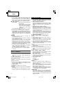
2. Grinding angle
Do not apply the entire surface of the depressed
center wheel to the material to be ground. As
shown in
Fig. 3
, the machine should be held at an
angle of 15° – 30° so that the external edge of the
depressed center wheel contacts the material at an
optimum angle.
3.
To prevent a new depressed center wheel from
digging into the workpiece, initial grinding should
be performed by drawing the grinder across the
workpiece toward the operator (
Fig. 3 direction B
).
Once the leading edge of the depressed center
wheel is properly abraded, grinding may be
conducted in either direction.
4. Switch operation
Switch ON: Push the locking button forward and
then press the switch lever.
* For continuous use, press the switch
lever. The switch lever is locked by
pushing the locking button forward
once again.
(*Subject to change depending on
area.)
Switch OFF: Press and release the switch lever.
5. Precautions immediately after finishing operation
After switching off the machine, do not put it down
until the depressed center wheel has come to a
complete stop. Apart from avoiding serious
accidents, this precaution will reduce the amount
of dust and swarf sucked into the machine.
CAUTIONS
䡬
Check that the work piece is properly supported.
䡬
Ensure that ventilation openings are kept clear when
working in dusty conditions.
If it should become necessary to clear dust, first
disconnect the tool from the mains supply (use non-
metallic objects) and avoid damaging internal parts.
䡬
Ensure that sparks resulting from use do not create
a hazard e.g. do not hit persons, or ignite flammable
substances.
䡬
Always use eye and ear protection.
Other personal protective equipment such as dust
mask, gloves, helmet and apron should be worn
when necessary.
If in doubt, wear the protective equipment.
䡬
When the machine is not use, the power source
should be disconnected.
ASSEMBLING AND DISASSEMBLING THE
DEPRESSED CENTER WHEEL
CAUTION
Be sure to switch OFF and disconnect the attachment
plug from the receptacle to avoid a serious accident.
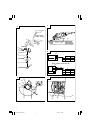
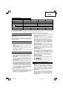
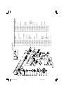
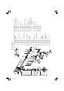
1. Assembling (Fig. 1)
(1) Turn the machine upside down so that the spindle
is facing upward.
(2) Mount the wheel washer onto the spindle.
(3) Fit the protruding part of the depressed center
wheel onto the wheel washer.
(4) Screw the wheel nut onto the spindle.
(5) Insert the push button to prevent rotation of the
spindle, and tighten the wheel nut with the accessory
wrench, as shown in
Fig. 1
.
2. Disassembling
Follow the above procedures in reverse.
CAUTIONS
䡬
Comfirm that the depressed center wheel is mounted
firmly.
䡬
Confirm that the push button is disengaged by
pushing push button two or three times before
switching the power tool on.
MAINTENANCE AND INSPECTION
1. Inspecting the depressed center wheel
Ensure that the depressed center wheel is free of
cracks and surface defects.
2. Inspecting the mounting screws
Regularly inspect all mounting screws and ensure
that they are properly tightened. Should any of the
screws be loose, retighten them immediately. Failure
to do so could result in serious hazard.
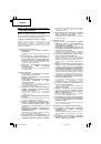
3. Inspecting the carbon brushes (Fig. 4)
The motor employs carbon brushes which are
consumable parts.
When they become worn to or near the “wear
limit”, it could result in motor trouble. When an
auto-stop carbon brush is equipped, the motor will
stop automatically.
At that time, replace both carbon brushes with new
ones which have the same carbon brush numbers
shown in the figure. In addition, always keep carbon
brushes clean and ensure that they slide freely
within the brush holders.
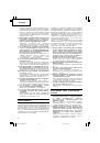
4. Replacing carbon brushes
G18SH2
•
G18U2
•
G23SF2
•
G23U2 (Fig. 5)
〈
Disassembly
〉
(1) Loosen the D4 tapping screw retaining the brush
cover and remove the brush cover.
(2) Use the auxiliary hexagonal wrench or small
screwdriver to pull up the edge of the spring that
is holding down the carbon brush. Remove the
edge of the spring toward the outside of the brush
holder.
(3) Remove the end of the pig-tail on the carbon brush
from the terminal section of brush holder and then
remove the carbon brush from the brush holder.
〈
Assembly
〉
(1) Insert the end of the pig-tail of the carbon brush
in the terminal section of brush holder.
(2) Insert the carbon brush in the brush holder.
(3) Use the auxiliary hexagonal wrench or small
screwdriver to return the edge of the spring to the
head of the carbon brush.
(4) Mount the tail cover and tighten the D4 tapping
screw.
01Eng_G18SH2_EE
11/30/09, 18:49
9