14
G
B
B
efore operating your new appliance please read
this instruction boo
k
let carefully. It contains
important information concerning the safe installation
and operation of the appliance.
Please
k
eep these operating instructions for future
reference. Ma
k
e sure that the instructions are
k
ept
with the appliance if it is sold, given away or moved.
The appliance must be installed by a qualified
professional in accordance with the instructions
provided.
Any necessary adjustment or maintenance must be
performed after the coo
k
er has been disconnected
from the electricity supply.
P
o
s
itionin
g
an
d
le
v
ellin
g
It is possible to install the appliance alongside
cupboards whose height does not e
x
ceed that of the
hob surface.
Ma
k
e sure that the wall in contact with the bac
k
of
the appliance is made from a non-flammable, heat-
resistant material (T 90°C).
To install the appliance correctly:
Place it in the
k
itchen, the dining room or the bed-
sit (not in the bathroom).
If the top of the hob is higher than the cupboards,
the appliance must be installed at least 600 mm
away from them.
If the coo
k
er is
installed underneath a
wall cabinet, there must
be a minimum distance
of 420 mm between
this cabinet and the top
of the hob.
This distance should
be increased to 700
mm if the wall cabinets
are flammable (
see figure
).
D
o not position blinds behind the coo
k
er or less
than 200 mm away from its sides.
Any hoods must be installed according to the
instructions listed in the relevant operating
manual.
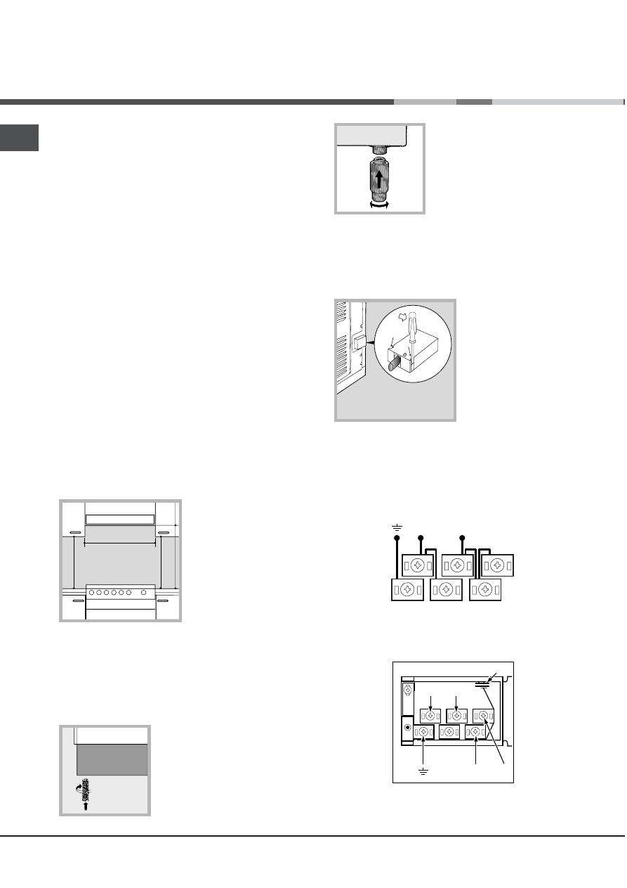
L
e
v
ellin
g
If it is necessary to level the
appliance, screw the
adjustable feet into the places
provided on each corner of the
base of the coo
k
er (
see
figure
).
The legs* fit into the slots on
the underside of the base of
the coo
k
er.
E
le
c
t
r
i
c
al
c
onne
c
tion
F
ittin
g
t
h
e
p
o
w
e
r
s
upp
l
y c
a
b
le
To open the terminal board:
Insert a screwdriver into the side tabs of the
terminal board cover.
Pull the cover to
open it.
To install the cable, follow the instructions below:
Loosen the cable clamp screw and the wire
contact screws.
The jumpers are pre-set at the Factory for 230 V
single-phase connection (
see figure
).
To carry out the electrical connections as shown in
the figures, use the two jumpers inside the bo
x
(
see figure
- labelled P).
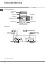
I
n
s
t
alla
t
ion
HOOD
420
Min.
min.
650
mm. with hood
min.
700
mm. without hood
mm.
600
Min.
mm.
420
Min.
mm.
*
O
n
l
y
a
v
a
il
a
ble
i
n
ce
r
t
a
i
n
mo
dels.
N
L2
L1
L3
P
N
L
230V 1N~
H07RN-F 3x4 CEI-UNEL 35364
1
3
2
4
5