Fremdspracheneinleger: Credo II
Ausgabe 08
/05
E
D
V-
Nr. 6902989
Assembly and operating instructions
I Technical
data
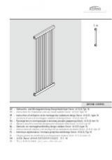
II Legend
A
Heating
area
BH
Actual construction height
BL
Actual construction length
BT
Construction depth
G
Weight
H
Clearance: Drill hole to pipe centre connection line
L
Drill hole spacing
n
Heater
exponent
NA
Hub clearance
NR
Article no.
P
Heating
capacity
P
1
Heating capacity electro rod
V
Water
content
III Side and rear view
IV Drill hole spacing
V Connections
Connections: 2 x G 3/4 (external thread) to rear.
Flow pipe possible both on corner valve and shut-off screw
connection, two-way valve flow
Ventilation: G 1/4 (internal thread) to rear.
VI Operation
Operating pressure: max. 10 bar
Test pressure: 13 bar
Operating conditions: Hot water to 110°C, electro auxiliary
operation possible.
VII Manufacturer’s instructions
Permissible usage
The heater shall only be used for heating indoor areas and for
the drying of textiles which have been washed in water. Each
and every other usage is not purpose-related and is therefore
not permissible!
Note:
Operating and water conditions should be observed according
to DIN 2035. Implementation in closed heating circuit systems.
Note:
Heaters supplied are intended solely for room heating. They
are not suitable as seating or as climbing or mounting aids.
Depending on the flow pipe temperature the heater surface
may heat up to 110°C.
Risk of burning!
Maintenance and cleaning
Bleed the heater following commissioning and extended
interruptions in operation.
For cleaning purposes, only mild and non-abrasive
commercially available cleaning agents may be used.
Complaints
In the event of damage, contact your specialised craftsman.
Attention!
Commission qualified tradesmen only to perform assembly and
repair jobs to assure that your rights according to the warranty
of quality law are not nullified!
Accessories
According to the currently valid sales documentation.
The instructions for installation and operation
are to be given to the final user !
VIII Assembly procedure
1 Read the instructions carefully prior to assembly!
2 Transport and storage shall only be carried out in the
protective packaging
3 Erection
site
Important
In the case of electro auxiliary operation the safety areas
prescribed in VDE 0100 part 701 must be observed (at the
heater side outside bath tub or shower area, socket and timer
at least 0.6 m away at the side).
4 Inspect the package content for completeness and
any possible damage!
A
Round tube heater
B
Corner
valve
C
Shut-off screw fitting
D
Shut-off screw fitting cover
E
Corner valve cover
F
Pre-mounted clip-on holder
G
Retaining
bolt
H
Plug
10x80
I
Vent
plug
J
Wall
rosette
K
Fixing
plates
L
Top securing cladding
M
Bottom securing cladding
N
Wall
holder
O
Snap
bolt
P
Screw
3.9x60
Q
Dowel
S6
R
Thermostat
head
S
Assembly
instructions
5 Have all tools at hand as required
6 Remove the protective foil only from the connection
and installation points. Otherwise, leave it on the
heater until it is commissioned.
7 Important:
Check the bearing surface for adequate supporting capacity!
Observe spacing requirements: Heater – side wall / room
ceiling min. 50mm !
8 Drill two horizontal dowel holes:
Diameter 10 mm, depth 80 mm, spacing “L“ (refer to IV
distance between drill holes)!
Danger to life !
Be careful not to damage any water or gas piping, or live
cables when drilling !
9
Insert dowel (H) in drill hole and screw in bolt (G) to
collar, align if necessary
.
10 Mount wall rosette (J) and fixing plate (K); then secure
wall rosette to the wall.
11 Screw in clip-on holder (F) by a few turns in the top
end of the heater and mount the heater on the
retaining bolt (G).
12 Push the heater to the wall and secure against falling
down by slightly tightening the M4 screws . The
screws engage in the bolt recess.
13 Mount securing cladding (M), insert in the wall
rosettes (J) and press into the pipe end.
14 Align heater
Adjust to the left/right, by means of M4 screws.
15 Adjust wall clearance by shifting along the bolt.
Height/depth adjustment by screw on the clip-on
holder.
Attention!
The marking on the screw must be within the header tube
projection.
16 Secure wall holder (N) in the centre on the bottom
transverse tube.
Press in the snap bolt
(O)
in the wall holder
(N)
and adjust in
such a way that the heater hangs vertically (if required, shorten
at preset breaking point). Mark the position of the snap bolt
plate
(O)
on the wall. Take off the heater again.
17 Drill a dowel hole.
Middle of the marking, diameter 6 mm, depth 60 mm
Danger to life !
Be careful not to damage any water or gas piping, or live
cables when drilling !
Insert the dowel
(Q)
in the drill hole.
Secure snap bolt
(O)
with screw
(P)
.
18 Mount heater again and secure by tightening the 4 x
M4 screws. Lock M8 screw in the clip-on holder by
means of a nut.
Screw tight!
19 Screw in vent plug.
20 Connect heater at the water side with corner valve
and return flow screw fitting.
Check the system for leaks!
21 Position wall rosettes correctly.
22 Mount securing cladding (L) and press into the header
tube.
23 Screw on thermostat head (R), clip on cover for the
flow and return pipe (E / D).
24 Dispose of packaging material via recycling systems.
Send scrap heaters with accessories for recycling or orderly
waste disposal as required (observe regional regulations).
Instructions de montage et de service
I Caractéristiques
techniques
II Légende
A
Surface
chauffante
BH
Hauteur de construction effective
BL
Longueur de construction effective
BT
Profondeur de construction
G
Poids
H
Ecart : Trou de perçage pour le centre de la conduite de
raccordement
L
Ecart entre les trous de perçage
n
Exposant
radiateur
NA
Ecart entre moyeux
NR
N° d’article
P
Puissance
calorifique
P
1
Puissance calorifique – barre électrique
V
Cubage
d’eau
III Vue latérale et arrière
IV Ecarts entre trous de perçage
V Raccords
Raccords : 2 x G 3/4 (filetage extérieur) vers l’arrière.
Conduite aller possible à la fois à la vanne d’angle et à la
connexion d’arrêt, vanne amorçable des deux côtés
Purge d’air : G 1/4 (filetage intérieur) vers l’arrière
VI Fonctionnement
Pression de service : max. 10 bar
Pression d’épreuve : 13 bar
Conditions de fonctionnement : Eau chaude jusqu’à 110°C,
fonctionnement électrique complémentaire possible.
VII Consignes du constructeur
Utilisation conforme
Le radiateur ne doit être utilisé que pour le chauffage de pièces
intérieures et pour le séchage de textiles lavés à l’eau. Toute
autre utilisation est non forme et par conséquent interdite.
Remarque :
Les conditions exploitation et eau doivent être observées
conformément à DIN 2035. Utilisation uniquement dans les
circuits de chauffage fermés.
Remarque :
Les radiateurs livrés servent exclusivement au chauffage de
pièces. Ils ne sont pas appropriés comme siège, estrade ou
escabeau.
Selon la température aller, la surface des radiateurs peut
chauffer jusqu’à 110 »C.
Risque de brûlure !
Entretien et nettoyage
Purgez l’air du radiateur après la mise en service et des
interruptions de fonctionnement prolongées.
Le nettoyage doit s’effectuer exclusivement avec des produits
du commerce doux et non agressifs.
Réclamations
Le cas échéant, adressez-vous à votre technicien spécialisé !
Attention !
Ne faites exécuter le montage et les réparations que par un
technicien spécialisé pour que vos droits à la garantie pour
défaut d’une qualité assurée restent valides.
Accessoires
Conformément aux documents de ventes actuellement en
vigueur.
Remettre les instructions de montage et de
service au client final !
VIII Déroulement du montage
1 Avant le montage, lire avec soin la notice !
2 Transport et stockage dans l’emballage de protection
uniquement !
3 Lieu de montage
Remarque
En mode de fonctionnement électrique complémentaire, les
zones de protection prescrites par la norme VDE 0100, partie
701, doivent être respectées (côté de radiateur en dehors de la
zone de baignoire ou de douche, prise et minuterie à au moins
0,6 m sur le côté).
4 Vérifier l’exhaustivité et les endommagements
éventuels du contenu de l’emballage !
A
Radiateur à tubes ronds
B
Vanne
d’angle
C
Connexion
d’arrêt
D
Cache de connexion d’arrêt
E
Cache de vanne d’angle
F
Support
enfichable
prémonté
G
Boulon de retenue
H
Cheville
10x80
I
Embout de purge d’air
J
Rosaces
murales
K
Rondelles de blocage
L
Habillage de fixation du haut
M
Habillage de fixation du bas
N
Support
mural
O
Axe à fixation immédiate
P
Vis
3.9x60
Q
Cheville
S6
R
Tête de thermostat
S
Notice
de
montage
5 Préparer l’outillage nécessaire
6 N’enlever la feuille plastique de protection que des
points de raccordement et de montage ; pour le reste,
la laisser en place sur le radiateur jusqu'à la mise en
service.
7 Important
Vérifier la capacité de charge du support !
Noter les écarts : au moins 50 mm entre le radiateur et le
mur/plafond !
8 Percer deux trous à l’horizontale pour les chevilles :
diamètre 10 mm, profondeur 80 mm, écart « L » (cf. IV Ecart
entre trous de perçage) !
Danger de mort !
Ne pas endommager de conduites d’eau, de gaz ou
d’électricité lors du perçage !
9 Insérer les chevilles (H) dans les trous de perçage et
enfoncer les boulons (G) jusqu’à l’embase ; les
aligner au besoin.
10 Installer la rosace murale (J) et la rondelle de blocage
(K), puis fixer la rosette au mur.
11 Visser de quelques pas de vis le support enfichable
(F) dans l’extrémité du radiateur et monter celui-ci sur
le boulon de retenue (G).
12 Pousser le radiateur contre le mur et le verrouiller
contre le chute en serrant légèrement les vis M4. Les
vis prennent dans le talon de boulon.
13 Enfiler les habillages de fixation (M), les insérer dans
les rosaces murales (J) et les enfoncer dans
l’extrémité de tube.
14 Aligner le radiateur
Réglage à gauche/à droite, avec les vis M4.
15 Réglage de l’écart mural par déplacement le long du
boulon. Réglage haut/bas par la vis sur le support
enfichable.
1