Fremdspracheneinleger: CHE1A
1
Ausgabe 08
/06
E
D
V-
Nr. 6904267
Assembly and operating instructions
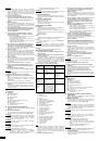
I Technical
data
II Legend
A
Heating
area
BH
actual construction height
BL
actual construction length
BT
Construction depth
G
Weight
H
Clearance: Drill hole to bottom edge of panel
L1, L2, L3
Drill hole spacing
NR
Article no.
P
Heating capacity electro rod
V
Water
content
III Side / Rear view and drill hole spacing
(right versíon as illustrated, left version mirror-imaged)
IV Service mode
Purely electrical operation, independent of the hot water heater
with controlling via WIR or WRT electro units.
Attention!
The heater shall not be operated with a damaged connecting
cable. The heating element may only be replaced by an
electrician according to BGV A2 (health and safety at workplace
regulation) !
Attention!
The electric heater must not be connected up to the central
heating system!
Attention!
Please observe the typeplate! The electric heater must only be
operated with the voltage specified on the typeplate.
Attention!
In the event of a leakage of heat carrier liquid:
–
Disconnect the appliance from the power immediately.
– Collect the liquid, put it into vessels with identification
marking, and dispose of according to statutory regulations
(ASN 54113)
–
Never replace escaped liquid with water.
–
Inform your specialised craftsman.
Attention!
In the event of fire
do not use water for extinguishing
! Use fire
extinguishers with carbon dioxide, foam, powder or with sand.
V Electrical
connection
Electrical heating element, below in the collecting pipe,
connection via mains connector or operating element.
VI Pressures / Filling
Operating pressure: max. 10 bar
Test pressure: 13 bar
Filling: special heat carrier liquid (without constituents which are
toxic or injurious to health).
VII Manufacturer´s instructions
Permissible usage
The heaters supplied are used exclusively for room heating and
drying water-dampened fabrics.
They are not suitable as seating, climbing or mounting aids.
Depending on the operating status, the heator surface may heat
up to 90°C.
Risk of burning!
Cleaning
For cleaning purposes, only mild and non-abrasive commercially
available cleaning agents may be used.
Complaints
In the event of damage, contact your specialised craftsman!
Attention!
Commission qualified tradesmen only to perform assembly and
repair jobs to assure that your rights according to the warranty of
quality law are not nullified!
Accessories
According to the currently valid sales documentation.
VIII Assembly procedure
1 Please read the instructions carefully prior to
assembly!
2 Transport and storage shall only be carried out in the
protective packaging!
3 Mounting
location
Do not mount the mains connector or operating element and
room heater in safety area 0 or 1! The mounting location should
be free of thermal interference (sunlight, lamp etc.). Please
observe the assembly and operating instructions for the
WIR
or
WRT
electro unit.
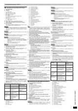
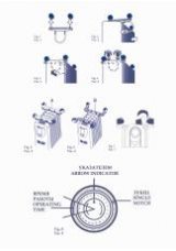
Safety areas according to VDE 0100 Part 701
Safety area
Definition
KERMI product
Bathroom heater
Area
0
and
1
No
connection of electric
room heaters permissible
Area
2
Connection of protection
class
IP x 4
electric
equipment
Bathroom heater incl.
electric heater and if
necessary IR
receiver
Outside the
safety areas in
the wetroom
Connection of protection
class
IP x 1
electric
equipment
IR transmitter
Electric
equipment in the
wetroom
Are permissible if they are
protected by a residual
current protective device
according to DIN
57664/VDE 0664
standard
4 Inspect the package content for completeness and any
possible damage!
A
Heater
A1
Wall anchor plate
A2
Panel
B
Wall
bracket
C
Wall bracket cladding
D
2-part spacer cladding
E
Hexagon nut DIN 936
F
Washer DIN 125
G
Set screw M8x8
H
Assembly
instructions
I
Conical disks DIN 6319
J
Conical sockets DIN 6319
K
Plug screw hex socket
L
Plug
10Lx80
M
Plug and screw for side support
N
Setscrew M4 x6
O
Spacer
P
rear clamping component
Q
front clamping component
R
Recessed head screw M6x25
S
Foot for side support
T
Slot
washer
U
Side
support
V
Snap
bolt
Note:
The securing material delivered with the unit is designed for use
in private buildings for adequately supporting bearing surfaces.
However, the securing method suitable in each case must
always be checked out locally and the securing material must
match the installation situation.
5 Have all tools at hand as required
6 Remove the protective foil only from the connection
and installation points. Otherwise, leave it on the heater
until it is commissioned.
7 Mount securing components
Turn setscrews M8x60
(G)
top left and right as far as they will go.
Secure wall bracket cladding
(C)
(slots to the front and bent
edges facing up) with two hexagon nuts DIN 936
(E)
.
8 Loosely screw rear clamping component (P) to front
clamping component (Q) in the middle of the bottom
cross tube gap with recessed head screw M6x25 (R).
9 Mount heater securing fittings (please refer to technical
data table for dimensions and illustration of the drill
hole spacings)
-
Secure wall bracket
(B)
to the wall with plug screw hex
socket
(K)
and plug 10Lx80
(L)
.
- Secure
spacer
(O)
to the wall with plug screw hex socket
(K)
and plug 10Lx80
(L)
.
-
Secure foot for side support
(S)
to the wall with plug and
screw
(M)
and slot washer
(T)
.
10 Screw on hexagon nuts DIN 936 (E) on left and right on
setscrews M8x60 (G) with approx. 5 mm play in relation
to the screws beneath.
Mount conical washers
(I)
and conical disks
(J)
in the illustrated
order on left and right.
11 Mount heater
Insert heater with the setscrews in the pre-mounted wall bracket
(B)
and in the spacer
(O)
from below.
Mount conical disks
(J)
and conical washers
(I)
in the illustrated
order on top at the left and right . Secure heater at the left and
right with hexagon nuts DIN 936
(E).
12 Align heater
Lock the lower securing point with setscrew M4x6
(N)
. Align the
heater to the connection lines along the slots and/or by adjusting
the hexagon head cap screws on the setscrews M8.
Then tighten the various securing screws.
13 Push on snap bolt (V) in foot for side support (S) and
secure with side support (U) to the heater.
14 Connect to electricity supply.
Please observe the assembly instructions for the
WIR
or
WRT
electro unit.
Attention:
Electrical connection may only be performed by a qualified
electrician!
15 Mount covers (D) for the spacers.
16 Mount wall anchor plate (A1) on panel end (A2).
Insert panel
(A2)
with the two fixtures at the top and bottom
between the heater cross tubes at the appropriate height.
Lock fixtures with a quarter turn respectively.
17 Dispose of packaging material via recycling systems.
Send scrap heaters with accessories for recycling or orderly
waste disposal as required (observe regional regulations).
Instructions de montage et de service
I Caractéristiques
techniques
II Légende
A
Surface
chauffante
BH
Hauteur de construction effective
BL
Longueur de construction effective
BT
Profondeur de construction
G
Poids
H
Ecart : Trou de perçage vers la bordure inférieure du cache
L1, L2, L3
Ecarts entre les trous de perçage
NR
N° d’article
P
Puissance calorifique – barre électrique
V
Cubage
d’eau
III Vue latérale / arrière et écarts entre trous de
perçage
(exécution de droite comme sur illustration, exécution de
gauche inversée)
IV Mode de fonctionnement
Fonctionnement électrique seul, indépendamment du chauffage
d’eau chaude avec commande via set électrique
WRT
ou
WIR
.
Attention !
Le radiateur ne doit pas fonctionner avec un câble de
raccordement endommagé ! L’élément chauffant ne doit être
remplacé que par un électricien conformément à BGV A2 !
Attention !
Le radiateur électrique ne doit pas être raccordé au système de
chauffage central !
Attention !
Observer la plaque signalétique ! Le radiateur électrique ne doit
fonctionner qu’à la tension spécifiée !
Attention !
En cas d'écoulement de fluide caloporteur :
–
débrancher immédiatement l’appareil du secteur
– collecter le liquide dans des conteneurs appropriés et
l’évacuer conformément aux prescriptions administratives
(ASN 54113)
–
ne jamais remplacer le fluide écoulé par de l’eau
–
informez votre concessionnaire.
Attention !
En cas d’incendie,
ne pas éteindre avec de l’eau
! Utilisez des
extincteurs au gaz carbonique, mousse, poudre ou du sable.
V Branchement
électrique
Elément chauffant électrique en bas dans le tube collecteur,
raccordement via élément de raccordement secteur resp. de
commande.
VI Pressions / remplissage
Pression de service : max. 10 bar
Pression d’épreuve : 13 bar
Remplissage
: fluide caloporteur spécial (sans composants
toxiques ou dangereux pour la santé)
VII Consignes du constructeur
Utilisation conforme
Les radiateurs livrés servent exclusivement au chauffage de
pièces et au séchage de textiles mouillés.
Ils ne sont pas appropriés comme siège, estrade ou escabeau.
Selon l’état de fonctionnement, la surface des radiateurs peut
chauffer jusqu’à 90 C.
Risque de brûlure !
Nettoyage
Le nettoyage doit s’effectuer exclusivement avec des produits du
commerce doux et non agressifs.
Réclamations
Le cas échéant, adressez-vous à votre technicien spécialisé !
Attention !
Ne faites exécuter le montage et les réparations que par un
technicien spécialisé pour que vos droits à la garantie pour
défaut d’une qualité assurée restent valides.
Accessoires
Conformément aux documents de ventes actuellement en
vigueur.
VIII Déroulement du montage
1 Avant le montage, lire avec soin la notice !
2 Transport et stockage dans l’emballage de protection
uniquement !
3 Lieu de montage
Ne pas utiliser l’élément de raccordement secteur resp. de
commande, ainsi que l'appareil de chauffage de pièce dans la
zone de protection 0 ou 1 ! Le lieu de montage ne doit pas être
soumis à des contraintes thermiques (rayons du soleil, lampe,
etc.). Observez les instructions de montage et d’utilisation du set
électrique
WRT
resp.
WIR
.
Zone de protection suivant VDE 0100 Teil 701
Zone de
protection
Définition
Produit KERMI
Radiateur de salle
de bains
Zones
0
et
1
Raccordement d’appareils
de chauffage de pièce
électriques
non
autorisé
Zone
2
Raccordement de
moyens d’exploitation
électriques de type de
protection
IP x 4
Radiateur de salle de
bains, y compris
chauffage électrique
et le cas échéant
récepteur IR
Hors de la zone
de protection
dans local
humide
Raccordement de
moyens d’exploitation
électriques de type de
protection
IP x 1
Emetteur IR
Appareils
électriques dans
local humide
Autorisés quand ils sont
protégés par un disjoncteur
à courant de défaut
(interrupteur FI) conforme
aux normes de la série DIN
57664/VDE 0664
4 Vérifier l’exhaustivité et les endommagements
éventuels du contenu de l’emballage !
A
Radiateur
A1
Rosace murale
A2
Cache
B
Console
murale
C
Habillage de console murale
D
Habillage d’entretoise en deux parties
E
Ecrou à six pans DIN 936
F
Rondelle DIN 125
G
Goupille
filetée
M8x60
H
Notice
de
montage
I
Rondelles coniques DIN 6319
J
Rondelles à rotule concave DIN 6319
K
Vis-cheville à six pans creux
L
Cheville
10Lx80
M
Cheville et vis pour appui latéral
N
Goupille filetée M4 x6
O
Entretoise
P
Elément de blocage arrière
Q
Elément de blocage avant
R
Vis à empreinte cruciforme M6x25
S
Pied pour appui latéral
T
Rondelle à trou oblong
U
Appui
latéral
V
Axe à fixation immédiate