Operation and settings
29
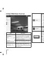
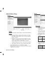
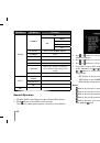
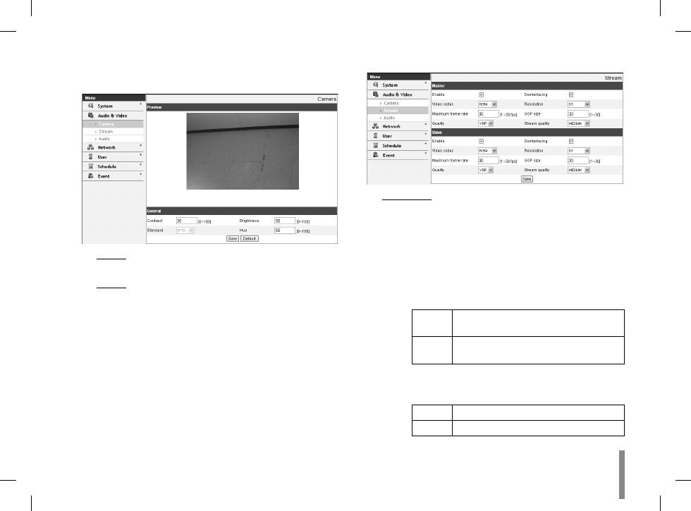
Audio & Video settings
Camera
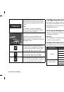
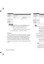
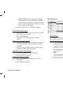
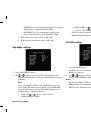
Preview
You can preview the camera image on the preview window.
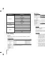
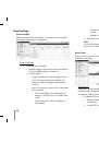
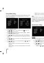
General
Contrast: Edit the contrast value in steps of 1, from
>
0 to 100. Selecting 100 provides the image with the
highest contrast.
Brightness: Edit to fine adjust the brightness of the
>
camera. It is brighter when a large value is selected
and it is darker when a small value is selected.
Standard: Displays the video standard of the camera.
>
Hue: Edit the video Hue of the camera from 0~100.
>
Save: Click this button to confirm the settings.
•
Default: Click this button to restore the IP device back to
•
original factory settings.
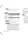
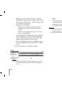
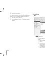
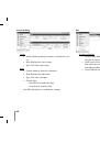
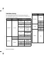
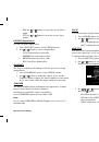
Stream
Master/Slave
Enable: Click to activate the stream function.
>
Deinterlacing: Click to enable the use of deinterlac-
>
ing function.
Video codec: Select the video mode (Codec) from
>
the drop-down list. The viewer can choose between
MPEG and H.264.
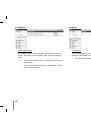
Resolution: Select the image size to be sent from the
>
camera.
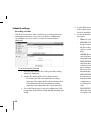
NTSC
D1 (704 x 480), HALF D1 (704 x 240),
CIF (352 x 240) and QCIF (176 x 112)
PAL
D1 (704 x 576), HALF D1 (704 x 288),
CIF (352 x 288) and QCIF (176 x 144)
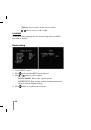
Maximum frame rate: Set the frame rate of the
>
image. Selectable values of the frame rates are as
follows.
NTSC
1 ~ 30 (fps)
PAL
1 ~ 25 (fps)