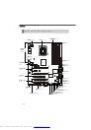
M S-7566 M ainboard
En-18
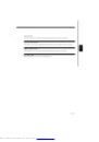
PIN
SIGNAL
DESCRIPTION
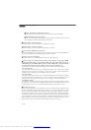
1
HD_LED +
Hard disk LED +
2
PWR/SLP LED
MSG LED
3
HD_LED -
Hard disk LED -
4
PWR/SLP LED
MSG LED
5
RST_SW -
Reset Switch -
6
PWR_SW +
Power Switch +
7
RST_SW +
Reset Switch +
8
PWR_SW -
Power Switch -
9
RSVD
Reserved. Do not use.
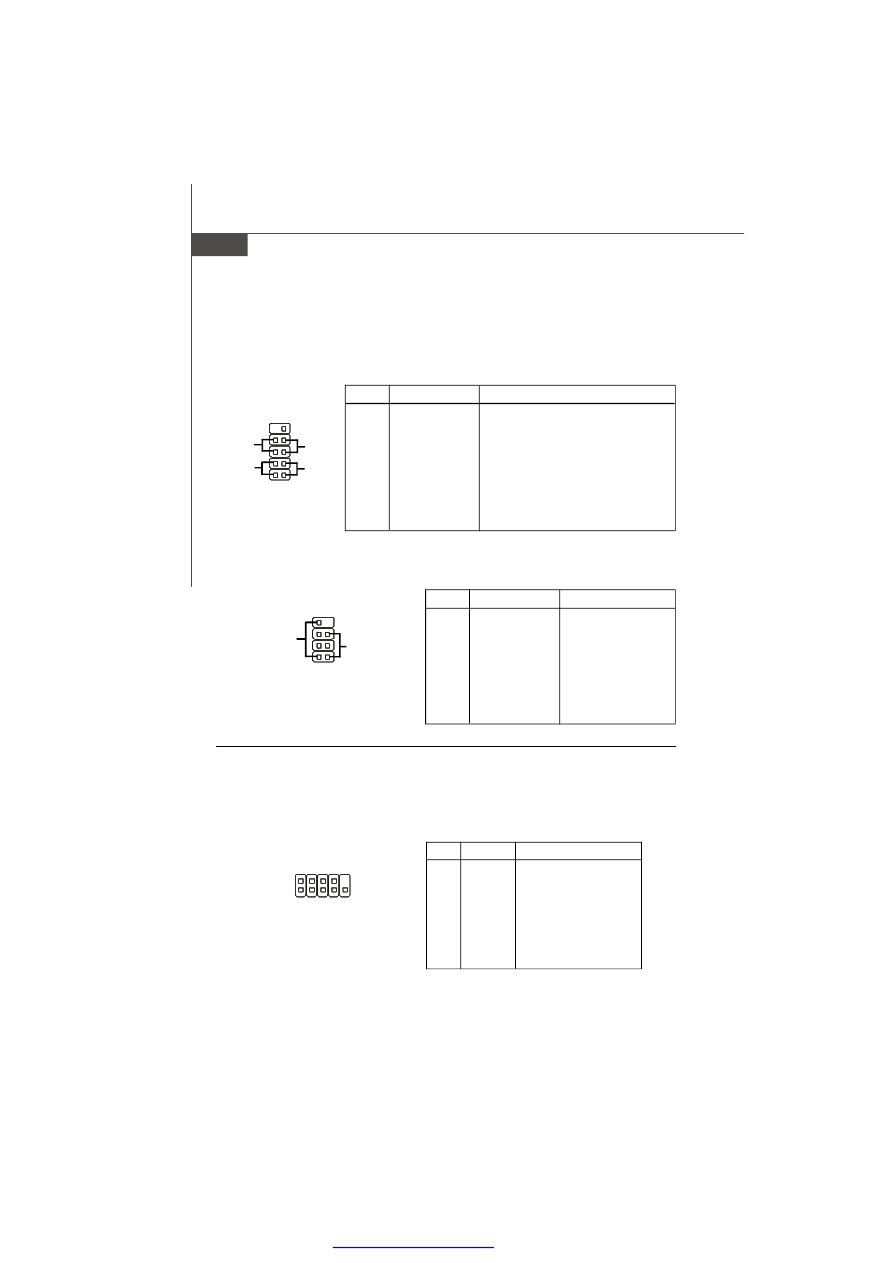
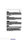
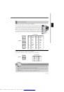
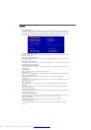
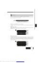
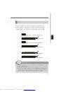
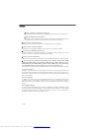
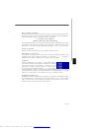
JFP1 Pin Definition
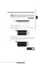
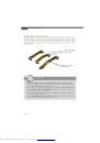
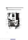
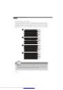
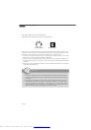
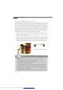
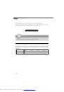
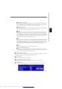
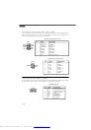
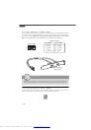
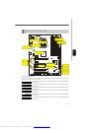
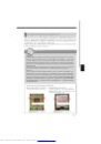
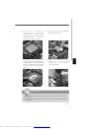
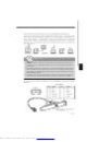
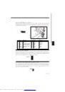
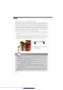
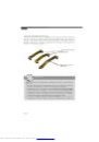
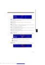
Front Panel Connectors: JFP1, JFP2
These connectors are for electrical connection to the front panel switches and LEDs.
The JFP1 is compliant with Intel
®
Front Panel I/O Connectivity Design Guide.
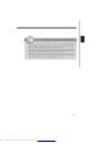
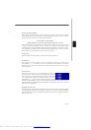
PIN
SIGNAL
DESCRIPTION
1
GND
Ground
2
SPK-
Speaker-
3
SLED
Suspend LED
4
BUZ+
Buzzer+
5
PLED
Power LED
6
BUZ-
Buzzer-
7
NC
Key (No Pin)
8
SPK+
Speaker+
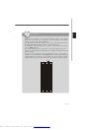
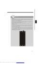
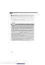
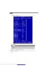
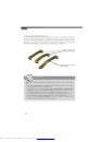
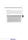
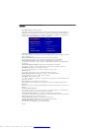
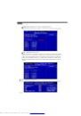
JFP2 Pin Definition
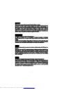
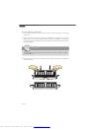
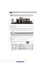
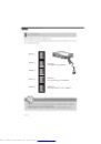
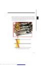
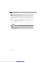
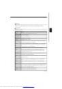
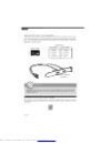
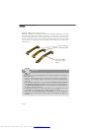
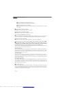
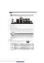
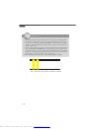
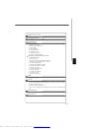
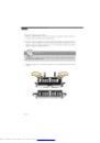
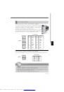
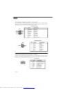
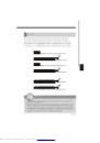
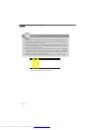
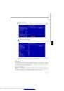
Serial Port Connector: JCOM1
This connector is a 16550A high speed communication port that sends/receives 16
bytes FIFOs. You can attach a serial device.
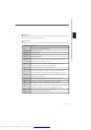
PIN
SIGNAL
DESCRIPTION
1
DCD
Data Carry Detect
2
SIN
Serial In or Receive Data
3
SOUT
Serial Out or Transmit Data
4
DTR
Data Terminal Ready
5
GND
Ground
6
DSR
Data Set Ready
7
RTS
Request To Send
8
CTS
Clear To Send
9
RI
Ring Indicate
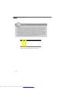
Pin Definition
JCOM1
1
9
2
10
1
2
9
10
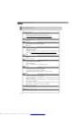
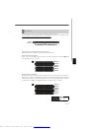
JFP1
HDD
LED
Reset
Switch
Power
LED
Power
Switch
+
+
+
-
-
-
7
8
Power
LED
Speaker
1
2
JFP2
+
+
-
-
PDF created with pdfFactory trial version
www.pdffactory.com
 1
1
 2
2
 3
3
 4
4
 5
5
 6
6
 7
7
 8
8
 9
9
 10
10
 11
11
 12
12
 13
13
 14
14
 15
15
 16
16
 17
17
 18
18
 19
19
 20
20
 21
21
 22
22
 23
23
 24
24
 25
25
 26
26
 27
27
 28
28
 29
29
 30
30
 31
31
 32
32
 33
33
 34
34
 35
35
 36
36
 37
37
 38
38
 39
39
 40
40
 41
41
 42
42
 43
43
 44
44
 45
45
 46
46
 47
47
 48
48
 49
49
 50
50
 51
51
 52
52
 53
53
 54
54
 55
55
 56
56
 57
57
 58
58
 59
59
 60
60
 61
61
 62
62
 63
63
 64
64
 65
65
 66
66
 67
67
 68
68
 69
69
 70
70
 71
71
 72
72
 73
73
 74
74
 75
75
 76
76
 77
77
 78
78
 79
79
 80
80
 81
81
 82
82
 83
83
 84
84
 85
85
 86
86
 87
87
 88
88
 89
89
 90
90
 91
91
 92
92
 93
93
 94
94
 95
95
 96
96
 97
97
 98
98
 99
99
 100
100
 101
101
 102
102
 103
103
 104
104
 105
105
 106
106
 107
107
 108
108
 109
109
 110
110
 111
111
 112
112
 113
113
 114
114
 115
115
 116
116
 117
117
 118
118
 119
119
 120
120
 121
121
 122
122
 123
123
 124
124
 125
125
 126
126
 127
127
 128
128
 129
129
 130
130
 131
131
 132
132
 133
133
 134
134
 135
135
 136
136
 137
137
 138
138
 139
139
 140
140
 141
141
 142
142
 143
143
 144
144
 145
145
 146
146
 147
147
 148
148
 149
149
 150
150
 151
151
 152
152
 153
153
 154
154
 155
155
 156
156
 157
157
 158
158
 159
159
 160
160
 161
161
 162
162
 163
163
 164
164
 165
165
 166
166
 167
167
 168
168
 169
169
 170
170
 171
171
 172
172
 173
173
 174
174
 175
175
 176
176
 177
177
 178
178
 179
179
 180
180
 181
181
 182
182
 183
183
 184
184
 185
185
 186
186
 187
187
 188
188
 189
189
 190
190
 191
191
 192
192
 193
193