2-16
M S-7376 M ainboard
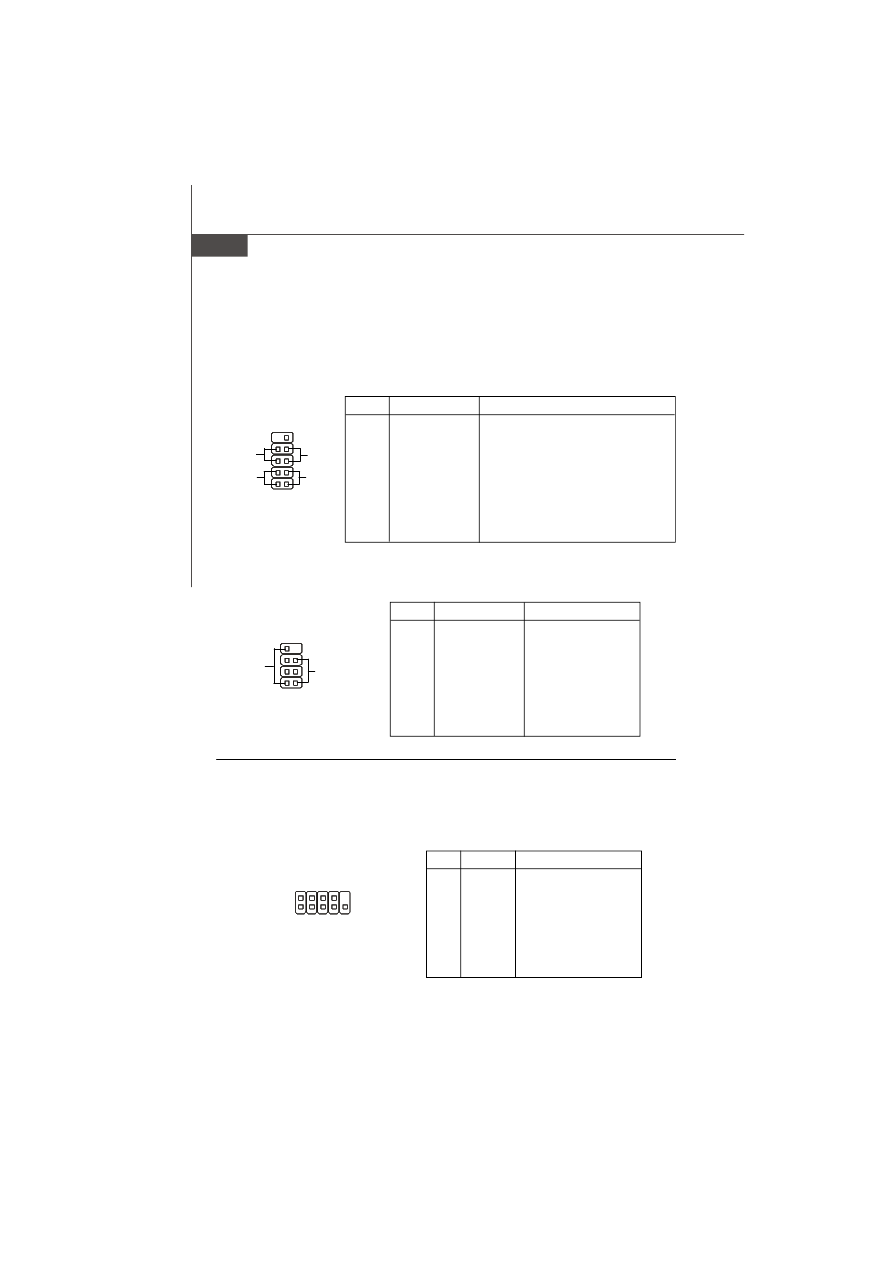
PIN
SIGNAL
DESCRIPTION
1
HD_LED +
Hard disk LED pull-up
2
FP PWR/SLP
MSG LED pull-up
3
HD_LED -
Hard disk active LED
4
FP PWR/SLP
MSG LED pull-up
5
RST_SW -
Reset Switch low reference pull-down to GND
6
PWR_SW +
Power Switch high reference pull-up
7
RST_SW +
Reset Switch high reference pull-up
8
PWR_SW -
Power Switch low reference pull-down to GND
9
RSVD_DNU
Reserved. Do not use.
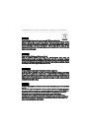
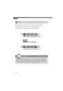
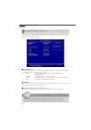
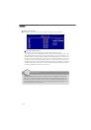
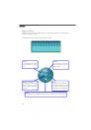
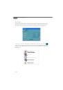
JFP1 Pin Definition
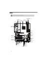
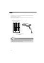
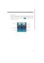
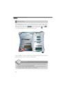
Front Panel Connectors: JFP1, JFP2
These connectors are for electrical connection to the front panel switches and LEDs.
The JFP1 is compliant with Intel
®
Front Panel I/O Connectivity Design Guide.
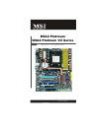
PIN
SIGNAL
DESCRIPTION
1
GND
Ground
2
SPK-
Speaker-
3
SLED
Suspend LED
4
BUZ+
Buzzer+
5
PLED
Power LED
6
BUZ-
Buzzer-
7
NC
No connection
8
SPK+
Speaker+
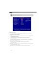
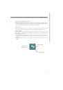
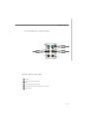
JFP2 Pin Definition
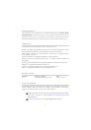
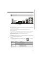
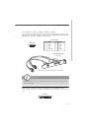
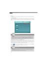
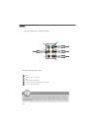
Serial Port Connector: JCOM1 (optional)
This connector is a 16550A high speed communication port that sends/receives 16
bytes FIFOs. You can attach a serial device.
PIN
SIGNAL
DESCRIPTION
1
DCD
Data Carry Detect
2
SIN
Serial In or Receive Data
3
SOUT
Serial Out or Transmit Data
4
DTR
Data Terminal Ready
5
GND
Ground
6
DSR
Data Set Ready
7
RTS
Request To Send
8
CTS
Clear To Send
9
RI
Ring Indicate
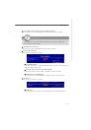
Pin Definition
JCOM1
1
9
2
1
2
9
10
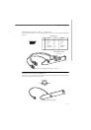
JFP1
HDD
LED
Reset
Switch
Power
LED
Power
Switch
+
+
+
-
-
-
7
8
Power
LED
Speaker
1
2
JFP2
+
+
-
-
 1
1
 2
2
 3
3
 4
4
 5
5
 6
6
 7
7
 8
8
 9
9
 10
10
 11
11
 12
12
 13
13
 14
14
 15
15
 16
16
 17
17
 18
18
 19
19
 20
20
 21
21
 22
22
 23
23
 24
24
 25
25
 26
26
 27
27
 28
28
 29
29
 30
30
 31
31
 32
32
 33
33
 34
34
 35
35
 36
36
 37
37
 38
38
 39
39
 40
40
 41
41
 42
42
 43
43
 44
44
 45
45
 46
46
 47
47
 48
48
 49
49
 50
50
 51
51
 52
52
 53
53
 54
54
 55
55
 56
56
 57
57
 58
58
 59
59
 60
60
 61
61
 62
62
 63
63
 64
64
 65
65
 66
66
 67
67
 68
68
 69
69
 70
70
 71
71
 72
72
 73
73
 74
74
 75
75
 76
76
 77
77
 78
78
 79
79
 80
80
 81
81
 82
82
 83
83
 84
84
 85
85
 86
86
 87
87
 88
88
 89
89
 90
90
 91
91
 92
92
 93
93
 94
94
 95
95
 96
96
 97
97
 98
98
 99
99
 100
100
 101
101
 102
102
 103
103
 104
104