DISCLAIMER – WARNING INFORMATION
Disclaimer – OmniMount Systems, Inc. has extended every effort to ensure to accuracy and completeness of this manual. However, OmniMount Systems, Inc. does not claim that the information covers all
installation or operational variables. The information contained in this document is subject to change without notice or obligation of any kind. Regarding the information contained herein, OmniMount Systems, Inc.
makes no representation of warranty, expressed or implied, and assumes no responsibility for accuracy, sufficiency, or completeness of the information contained in this document.
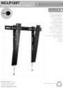
Wall Mounts
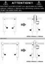
WARNING: FAILURE TO READ, THOROUGHLY UNDERSTAND, AND FOLLOW ALL INSTRUCTIONS CAN RESULT IN SERIOUS PERSONAL INJURY, DAMAGE TO PERSONAL PROPERTY, OR VOIDING OF
FACTORY WARRANTY!
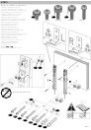
It is the responsibility of the installer to ensure all components are properly assembled and installed using the instructions provided. If you do not understand these instructions or have any questions or concerns, please
contact customer service at 1-800-668-6848 or info@omnimount.com.
Do not attempt to install or assemble this product if the product or hardware is damaged or missing. In the event that replacement parts or hardware are needed, please contact Customer Service at 1-800-668-6848 or
info@omnimount.com
. International customers needing assistance should contact the Dealer from which they purchased the product.
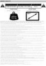
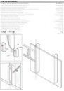
The included hardware is designed for use on vertical walls constructed of wood studs or solid concrete. A wood stud wall is defined as consisting of a minimum of 2x4 wooden studs (2” wide by 4” deep) with a
maximum of 5/8” drywall. The included hardware is not designed for use with metal studs or cinderblock walls. If you’re uncertain about the construction of your wall, then please consult a qualified contractor or
installer for assistance. For a safe installation, the wall you are mounting to must support 4 times the weight of the total load. If not, then the surface must be reinforced to meet this standard. The installer is responsible
for verifying that the wall structure and hardware used in any installation method will safely support the total load.
Descargo de responsabilidad. OmniMount Systems, Inc. ha puesto el máximo esfuerzo para que este manual sea preciso y completo. No obstante, no garantiza que la información aquí incluida cubra todos los
detalles, condiciones o variantes. Tampoco prevé todas las posibles contingencias relacionadas con la instalación o el uso de este producto. La información que contiene este documento queda sujeta a cambio sin
aviso previo o compromiso alguno. OmniMount Systems, Inc. no ofrece ninguna garantía, ni expresa ni implícita, respecto de la información aquí incluida. OmniMount Systems, Inc. no se responsabiliza de la precisión
de la información provista en este documento, ni tampoco de que sea completa o suficiente.
Soportes de pared
ADVERTENCIA: NO LEER, ENTENDER CABALMENTE O SEGUIR TODAS LAS INSTRUCCIONES PUEDE DERIVAR EN LESIONES GRAVES, DAÑOS MATERIALES O LA NULIDAD DE LA GARANTÍA
OTORGADA POR EL FABRICANTE.
Es responsabilidad del instalador comprobar que todos los componentes estén correctamente ensamblados e instalados según las instrucciones provistas. Si usted no entiende estas instrucciones o si tiene dudas o
preguntas, comuníquese con Atención al Cliente por teléfono al 1-800-668-6848 o por escrito a info@omnimount.com.
No instale ni ensamble el producto si éste o las piezas suministradas presentaran daños o si faltara algún elemento. Si necesita repuestos o piezas, comuníquese con Atención al Cliente por teléfono al 1-800-668-6848
o por escrito a
info@omnimount.com
. Si reside en otro país, comuníquese con la tienda donde compró el producto.
Las piezas incluidas están diseñadas para ser instaladas en paredes con paneles de madera o en paredes de hormigón. Se define como pared con vigas de madera aquélla conformada por vigas de madera de 51 mm
(2 pulgadas) de ancho por 102 mm (4 pulgadas) de profundidad como mínimo y por paneles de yeso de 16 mm (5/8 pulgada) de espesor como máximo. Las piezas incluidas no están diseñadas para instalarse en
paredes con vigas de metal ni en paredes de bloques de hormigón. Si tiene dudas acerca del tipo de pared que tiene usted, consulte a un contratista o a un instalador calificado. Para realizar una instalación segura, la
pared elegida debe poder soportar cuatro veces el peso de la carga total. De lo contrario, deberá reforzar la superficie para que cumpla con este requisito. El instalador es el responsable de comprobar que la
estructura de la pared y las piezas utilizadas en la instalación soporten la carga total de manera segura.
ESPAÑOL
Dénégation de responsabilité – OmniMount Systems, Inc. vise l’exactitude et la complétude du présent manuel, toutefois, ne prétend en aucun cas que les informations contenues dans le présent document
couvrent tous les détails, conditions ou variations. L’entreprise ne prévoit pas non plus tous les cas de figures possibles liés à l’installation ou à l’utilisation de ce produit. Les informations contenues dans le présent
document sont sujettes à modification sans préavis, ni obligation quelconque. OmniMount Systems, Inc. ne fait aucune déclaration quant à une garantie expresse ou implicite concernant les informations contenues
dans le présent document. OmniMount Systems, Inc. n’est en aucun cas responsable de l’exactitude, de l’exhaustivité, ni de la suffisance des informations contenues dans le présent document.
Supports muraux
ATTENTION : SI VOUS NE LISEZ, NI NE COMPRENEZ, NI NE SUIVEZ SOIGNEUSEMENT TOUTES CES INSTRUCTIONS, IL POURRAIT S’ENSUIVRE DES BLESSURES GRAVES, DES DOMMAGES MATÉRIELS
OU L’ANNULATION DE LA GARANTIE!
L'installateur est responsable de s’assurer de l’exactitude de l’assemblage et de l’installation de toutes les composantes, conformément aux instructions fournies. Si vous ne comprenez pas ces instructions ou pour
toute question ou problème, veuillez contacter le service à la clientèle au 1-800-668-6848 ou info@omnimount.com.
Si le produit est endommagé ou que des fixations sont manquantes ou endommagées, n'installez pas le produit. Si vous avez besoin de pièces ou de quincaillerie de rechange, veuillez contacter le Service à la clientèle
au 1-800-668-6848 ou
info@omnimount.com
. Pour les clients internationaux, contactez le détaillant auprès duquel vous avez acheté le produit.
La quincaillerie fournie est conçue pour servir sur des parois verticales en bois ou en béton massif. Un mur à poteau en bois est défini comme constitué au minimum de poteaux de 2x4 (51 mm ou 2 po de large par
102 mm ou 4 po de profondeur) avec un maximum de 16 mm (5/8 po) de cloison sèche. La quincaillerie incluse n’est pas conçue pour servir sur des poteaux métalliques, ni des murs en briques de mâchefer. Si vous
n’êtes pas sûr de la construction de votre mur, veuillez consulter un maître d’œuvre ou installateur qualifié pour obtenir de l'aide. Pour que l'installation soit sécuritaire, le mur d'installation doit pouvoir supporter 4 fois le
poids de la charge appliquée. Si tel n'est pas le cas, la surface doit être renforcée en conséquence. L'installateur doit s'assurer que la structure du mur et la quincaillerie utilisée pour n’importe quelle méthode de fixation
peuvent supporter sans danger le poids de tous les équipements.
FRANÇAIS
QUESTIONS?
1-800-MOUNT-IT (1-800-668-6848)
1-800-MOUNT-IT
(USA ONLY)
NEED HELP? PLEASE CALL
¿NECESITA AYUDA? LLÁMENOS.
BESOIN D’AIDE? VEUILLEZ APPELER
BRAUCHEN SIE HILFE? RUFEN SIE UNS BITTE AN
HULP NODIG? BEL DAN MET
SEVE AIUTO? CHIAMARE
POTRZEBUJESZ POMOCY? ZADZWOŃ
POTŘEBUJETE POMOC? ZAVOLEJTE NÁM
SEGÍTSÉGRE VAN SZÜKSÉGE? TELEFONÁLJON!
ΧΡΕΙΑΖΕΣΤΕ ΒΟΗΘΕΙΑ; ΠΑΡΑΚΑΛΟΎΜΕ ΚΑΛΈΣΤΕ
PRECISA DE AJUDA? CONTACTE
BRUG FOR HJÆLP? RING TIL
TARVITSETKO APUA? SOITA
BEHÖVER DU HJÄLP? RING
AVEŢI NEVOIE DE AJUTOR? SUNAŢI
НУЖДАЕТЕ СЕ ОТ ПОМОЩ? МОЛЯ, ОБАДЕТЕ СЕ
VAJATE ABI? PALUN HELISTAGE
NEPIECIEŠAMA PALĪDZĪBA? LŪDZU, ZVANIET
REIKIA PAGALBOS? SKAMBINKITE
ALI POTREBUJETE POMOČ? PROSIMO, POKLIČITE.
POTREBUJETE POMOC? PROSÍM, VOLAJTE
НУЖНА ПОМОЩЬ? ЗВОНИТЕ
YARDIM MI LAZIM? LÜTFEN BIZI ARAYIN
TRENGER DU HJELP? RING OSS
اذإ ﺖﻨآ ﺔﺟﺎﺤﺑ ءﺎﺟﺮﻟﺎﻓ ،ةﺪﻋﺎﺴﻤﻠﻟ لﺎﺼﺗﻻا.
您需要帮助吗?请致电
ご質問がある場合は、お電話ください