MANUEL D’INST
ALLA
TION
INST
ALLA
TION MANUAL
DEH-3000MP
<YRD5137-A/N> 1
<KMMZX> <07H00000>
Printed in Thailand
Imprimé en Thaïlande
<YRD5137-A/N> EW
<YRD5137-A/N> 1
Important
! Check all connections and systems before
final installation.
! Do not use unauthorized parts. Use of un-
authorized parts may cause malfunctions.
! Consult your dealer if installation requires dril-
ling of holes or other modifications to the vehi-
cle.
! Do not install this unit where :
— it may interfere with operation of the vehi-
cle.
— it may cause injury to a passenger as a re-
sult of a sudden stop.
! The semiconductor laser will be damaged if it
overheats. Install this unit away from hot
places such as near the heater outlet.
! Optimum performance is obtained when the
unit is installed at an angle of less than 60°.
60°
DIN front/rear mount
This unit can be properly installed either from
“Front” (conventional DIN front-mount) or
“Rear” (DIN rear-mount installation, utilizing
threaded screw holes at the sides of unit chas-
sis). For details, refer to the following installa-
tion methods.
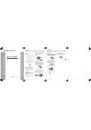
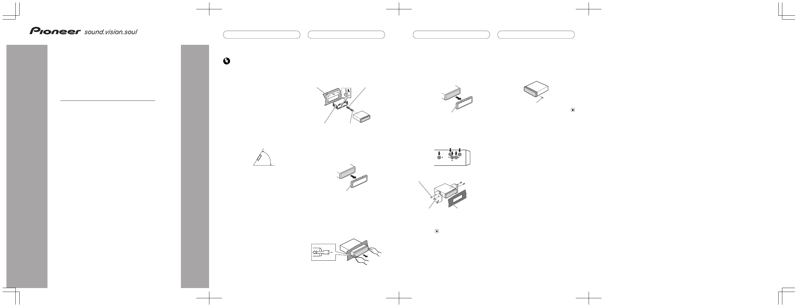
DIN Front-mount
Installation with the rubber bush
1
Insert the mounting sleeve into the
dashboard.
When installing in a shallow space, use a sup-
plied mounting sleeve. If there is enough
space behind the unit, use factory supplied
mounting sleeve.
2
Secure the mounting sleeve by using a
screwdriver to bend the metal tabs (90°)
into place.
3
Install the unit.
Dashboard
Rubber bush
Mounting sleeve
Screw
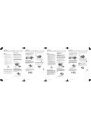
Removing the unit
1
Extend top and bottom of the trim ring
outwards to remove the trim ring. (When
reattaching the trim ring, point the side
with a groove downwards and attach it.)
Trim ring
! It becomes easy to remove the trim ring if
the front panel is released.
2
Insert the supplied extraction keys into
both sides of the unit until they click into
place.
3
Pull the unit out of the dashboard.
<YRD5137-A/N>3
Installation
En
<YRD5137-A/N> 2
DIN Rear-mount
1
Extend top and bottom of the trim ring
outwards to remove the trim ring. (When
reattaching the trim ring, point the side
with a groove downwards and attach it.)
Trim ring
! It becomes easy to remove the trim ring if
the front panel is released.
2
Determine the appropriate position
where the holes on the bracket and the
side of the unit match.
3
Tighten two screws on each side.
Screw
Mounting bracket
Dashboard or console
! Use either truss screws (5 mm × 8 mm) or
flush surface screws (5 mm × 9 mm), de-
pending on the shape of screw holes in the
bracket.
Fastening the front panel
If you do not plan to detach the front panel,
the front panel can be fastened with supplied
screw.
Screw
<YRD5137-A/N>4
Installation
En
<YRD5137-A/N> 3
<YRD5137-A/N>34
<YRD5137-A/N> 4