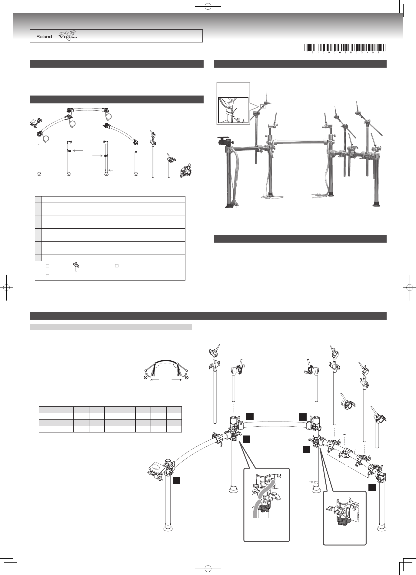
• Position the cable in front
• Align to position of
Height Memory
Align to position of
Height Memory
H
H
H
J
A
D
E
F
I
I
I
I
G
J
B
B
C
NOTE
The factory setting of the rod
angle is different only for the
Tom 2 mount.
Label
1
2
3
4
5
6
Before using this unit, carefully read the sections entitled: “
USING THE UNIT SAFELY
” and “
IMPORTANT NOTES
” (separate sheet). These sections provide
important information concerning the proper operation of the unit. Additionally, in order to feel assured that you have gained a good grasp of every feature
provided by your new unit, Owner’s manual should be read in its entirety. The manual should be saved and kept on hand as a convenient reference.
Copyright © 2009 ROLAND CORPORATION
All rights reserved. No part of this publication may be reproduced in
any form without the written permission of ROLAND CORPORATION.
Drum Stand
Owner’s Manual
MDS-25
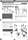
Components
Main Features
Setting Up The Stand
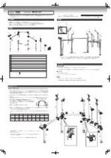
Fully Assembled View
Specifications
We recommend using an optional Roland drum mat (TDM series) to prevent scarring or discoloration of flooring
*
by the rubber feet of the stand.
A very solid and stable stand featuring ball clamps that allow precise adjustments for all pads
*
and cymbals.
Cables are inside the pipes, providing a clean look and quick breakdown or setup.
*
Important in Setting Up the Stand
Make sure to firmly tighten all hand knobs and bolts after you have assembled the stand and attached any compo-
*
nents. You should probably also try to make a habit of checking and retightening them if necessary before every
performance. You risk injury if you have loose screws or clamps, since a pad or component can fall unexpectedly.
When setting up or storing the stand, be careful not to pinch your hands or fingers in the stand joints.
*
Do not apply undue force to the hand knobs, pipes, mounts, etc.
*
Do not open the stand wider than 120 degrees outward. Be sure
*
the
two pipes at the ends tare no more than 1.6 meters apart. Doing so can
damage the cables inside the stand or cause the stand to fall over.
Never pull on any cables with excessive force.
*
There are labels on the ends of the cables allowing easy connection to your sound module.
*
For about connections, refer to the owners manual that came with your sound module.
1.6 m (63”)
120˚
120˚
View of Stand When Spread Open
Label
KIK
SNR
T1
T2
T3
T4
HH
HHC
Jack
KICK
SNARE
TOM 1
TOM 2
TOM 3
TOM 4
HI-HAT
HH CTRL
Label
CR1
CR2
RD
RDE
AX1
AX2
AX3
AX4
Jack
CRASH1
CRASH2
RIDE
EDGE
AUX 1
AUX 2
AUX 3
AUX 4
The names on the labels correspond to trigger input jack names as follows.
(input names shown here are for the TD-20X modules)
H
I
J
A
B
C
D
E
F
G
Height memory
Sound module mounting pipe including the mounting plate
A
Curved pipe L 750mm, Center pipe 600 mm (connection cables are inside)
B
Curved pipe R
C
Straight pipe 630 mm
D
Straight pipe 650 mm L
E
Straight pipe 650 mm R
F
Straight pipe 500 mm
G
Cymbal arm x 3
H
Pad arm x 4
I
Holder x 5
J
Drum key
Cable tie
Owner´s manual (this leaflet)
Label
750 mm
600 mm
Use the cable clips as
shown below, to secure
the cables.
Cable clip
Cable
Required Space for Set-up
•
1,400 (W) x 950 (D) x 1,100 (H) mm / 55-1/8 (W) x 37-7/16 (D) x 43-5/16 (H) inches (Drum Stand only)
1,600 (W) x 1,400 (D) x 1,250 (H) mm / 63 (W) x 55-1/8 (D) x 49-1/4 (H) inches
(including Sound Module, Kick Pad, Cymbals and Stool)
Tube Diameter
•
Stand: 38.1 mm / 1-1/2 inches
Pad Arm/Cymbal Arm: 22.2 mm / 7/8 inches
Weight
•
20.5 kg / 45 lbs 4 oz (including Pad Mounts and Cymbal Mounts)
In the interest of product improvement, the specifications and/ or appearance of this unit are subject to change without prior
*
notice.
View of Stand When Spread Open
•
Working in order, following numbers 1–6 in the illustration, attach the curved pipes to
the straight pipes.
Of pipes “B,” the long one (750 mm) is Curved Pipe L, and the shorter one (600 mm)
*
is the Center Pipe.
Do not pass any cables through pipe “C” (Curved Pipe R).
*