Rules For Safe Operation (2)
7
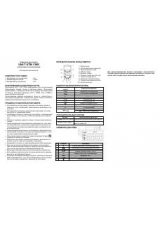
Model UT10A: OPERATING MANUAL
When the Meter working at an effective voltage over 60V in
DC or 30V rms
in AC, special care should be taken for there is danger of electric shock.
Use the proper terminals, function, and range for your measurements.
Do not use or store the Meter in an environment of high temperature, humidity,
explosive, inflammable and strong magnetic field. The performance of the
Meter may deteriorate after dampened.
When using the test leads, keep your fingers behind the finger guards.
Disconnect circuit power and discharge all high-voltage capacitors before
testing resistance, continuity, diodes or capacitance.
Replace the battery as soon as the battery indicator appears. With a low
battery, the Meter might produce false readings that can lead to electric
shock and personal injury.
Remove the connection between the testing leads and the circuit being
tested, and turn the Meter power off before opening the Meter case.
l
l
l
l
l
l
l