120
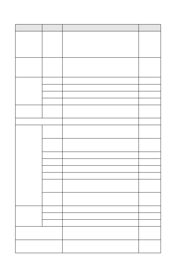
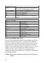
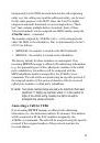
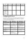
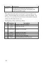
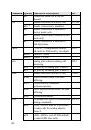
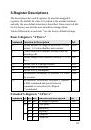
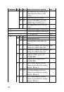
Command Options Function & Description
Ref.
KSxn
n=0-63
*0
Sub-persist time interval for BOD;
BOD disabled if n=0
x= M(in Minute unit) or S(in
Second unit)
S125b1-7
Ln
n=0-3
2 *
Speaker volume control. The
higher the value, the higher the
volume
S24.4-5
Mn
M=0-2
Speaker control
S21.1-2
M0
Speaker always OFF
M1 *
Speaker ON until call is answered
M2
Speaker always ON
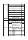
Nn
n=0-3
3 *
Ring volume control.'N0' will
disable the audio ring function
S24.0-1
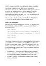
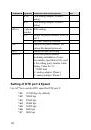
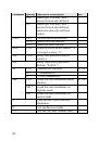
O
Return to on-line state
Pn
n=0-6
D channel protocol selection
(USA) for American Version
S86
P0 *
Northern Telecom proprietary
ISDN
P1
National ISDN 1 (1 SPID)
P2
National ISDN 1 (2 SPID)
P3
Reserved
P4
AT&T custom point-to-point
P5
AT&T custom point-to-multipoint
(1 SPID)
P6
AT&T custom point-to-multipoint
(2 SPID)
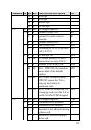
Qn
n=0-1
Result code displayed
S23.7
Q0 *
TA returns result code
Q1
TA does not return result code
Sr.b=n
Set bit 'b' of S-register 'r' to value
'n'. 'n' is a binary digit '0' or '1'
Sr.b?
Display value of bit 'b' of S-register
'r'
 1
1
 2
2
 3
3
 4
4
 5
5
 6
6
 7
7
 8
8
 9
9
 10
10
 11
11
 12
12
 13
13
 14
14
 15
15
 16
16
 17
17
 18
18
 19
19
 20
20
 21
21
 22
22
 23
23
 24
24
 25
25
 26
26
 27
27
 28
28
 29
29
 30
30
 31
31
 32
32
 33
33
 34
34
 35
35
 36
36
 37
37
 38
38
 39
39
 40
40
 41
41
 42
42
 43
43
 44
44
 45
45
 46
46
 47
47
 48
48
 49
49
 50
50
 51
51
 52
52
 53
53
 54
54
 55
55
 56
56
 57
57
 58
58
 59
59
 60
60
 61
61
 62
62
 63
63
 64
64
 65
65
 66
66
 67
67
 68
68
 69
69
 70
70
 71
71
 72
72
 73
73
 74
74
 75
75
 76
76
 77
77
 78
78
 79
79
 80
80
 81
81
 82
82
 83
83
 84
84
 85
85
 86
86
 87
87
 88
88
 89
89
 90
90
 91
91
 92
92
 93
93
 94
94
 95
95
 96
96
 97
97
 98
98
 99
99
 100
100
 101
101
 102
102
 103
103
 104
104
 105
105
 106
106
 107
107
 108
108
 109
109
 110
110
 111
111
 112
112
 113
113
 114
114
 115
115
 116
116
 117
117
 118
118
 119
119
 120
120
 121
121
 122
122
 123
123
 124
124
 125
125
 126
126
 127
127
 128
128
 129
129
 130
130
 131
131
 132
132
 133
133
 134
134
 135
135
 136
136
 137
137
 138
138
 139
139
 140
140
 141
141
 142
142
 143
143
 144
144
 145
145
 146
146
 147
147
 148
148
 149
149
 150
150
 151
151
 152
152
 153
153
 154
154
 155
155
 156
156
 157
157
 158
158
 159
159
 160
160
 161
161
 162
162
 163
163
 164
164
 165
165
 166
166
 167
167
 168
168
 169
169
 170
170
 171
171
 172
172
 173
173