4
GB
Fixing
The appliance must be installed
on a perfectly level
supporting surface.
Any deformities caused by improper fixing could affect
the features and operation of the hob.
The thickness of the supporting surface
should be taken
into account when choosing
the length of the screws for
the fixing hooks:
• 30 mm thick: 17.5 mm screws
• 40 mm thick: 7.5 mm screws
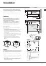
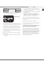
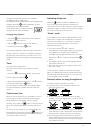
Fix the hob as follows:
1. Use short flat-bottomed screws to fix the 4 alignment
springs in the holes provided at the central point of
each side of the hob.
2. Place the hob in the cavity, make sure it is in a
central position and push down on the whole perimeter
until the hob is stuck to the supporting surface.
3. For hobs with raised sides: After inserting the hob
into its cavity, insert the 4 fixing hooks (each has its
own pin) into the lower edges of the hob, using the
long pointed screws to fix them in place, until the glass
is stuck to the supporting surface.
!
The screws for the alignment springs must remain
accessible.
!
In order to adhere to safety standards, the appliance
must not come into contact with electrical parts once it
has been installed.
!
All parts which ensure the safe operation of the
appliance must not be removable without the aid of a
tool.
Electrical connection
!
The electrical connection for the hob and for any built-
in oven must be carried out separately, both for safety
purposes and to make extracting the oven easier.
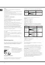
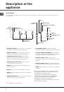
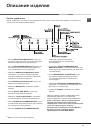
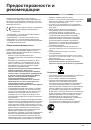
Terminal board
On the lower part of the appliance there is a
connection box for the different
types of electricity supply (the
picture is only an indication and
is not an exact representation
of the purchased model).
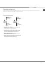
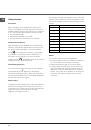
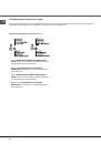
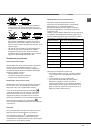
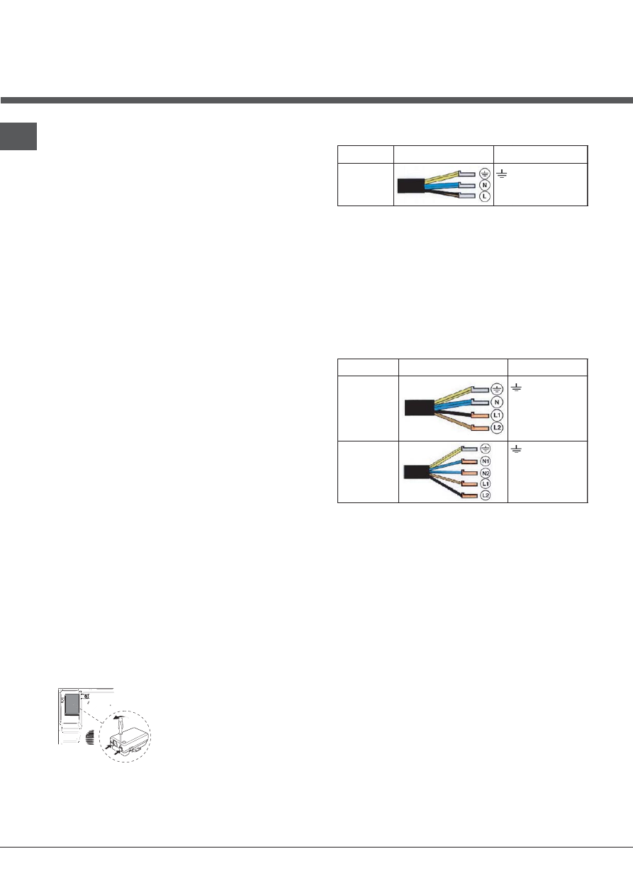
Single-phase connection
The hob is equipped with a pre-connected electricity
supply cable, which is designed for single-phase
connection. Connect the wires in accordance with the
instructions given in the following table and diagrams:
Voltage and
mains frequency
Electrical cable
Wire connection
230-240V 1+N ~
220-240V 1+N ~
50/60 Hz
: yellow/green
N
: the two blue wires together
L
: brown and black together
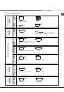
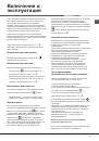
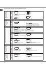
Other types of connection
If the mains supply corresponds with one of the
following:
Voltage and mains frequency
• 400V - 2+N ~ 50/60 Hz
• 220-240V 3 ~ 50/60 Hz
• 230-240V 3 ~ 50/60 Hz
• 400V - 2+2N ~ 50/60 Hz
Separate the wires and connect them in accordance
with the instructions given in the following table and
diagrams:
Voltage and
mains frequency
Electrical cable
Wire connection
400V - 2+N ~
50/60 Hz
230-240V 3 ~
220-240V 3 ~
50/60 Hz
: yellow/green;
N
: the two blue wires
together
L1
: black
L2
: brown
400V - 2+2N ~
50/60 Hz
: yellow/green;
N1
: blue
N2
: blue
L1
: black
L2
: brown
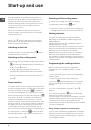
If the mains supply corresponds with one of the
following:
Voltage and mains frequency
• 400V 3 - N ~ 50/60 Hz
proceed as follows:
!
The cable provided is not suitable for the following
types of installation.
1. Use a suitable supply cable, H05RR-F or higher, with
the right dimensions (cable cross section: 25 mm).
2. To open the terminal board, use a screwdriver as
a lever under the side tabs of the cover (
see Terminal
board picture
).
3. Loosen the cable clamp screw and the terminal
board screws in accordance with the type of
connection required and position the connection
supports as shown in the following table and diagrams.
4. Position the wires in accordance with the information
given in the following table and diagrams and connect
the appliance by tightening all the screws for the
springs as much as possible.
UNDERSIDE OF HOB