19
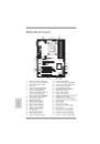
ASRock FM2A85X Extreme4 Motherboard
English
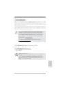
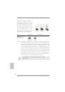
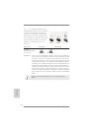
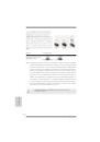
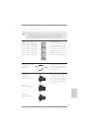
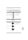
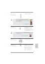
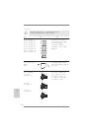
2.4 Expansion Slots (PCI and PCI Express Slots)
There are 3 PCI slots and 4 PCI Express slots on this motherboard.
PCI Slots: PCI slots are used to install expansion cards that have the 32-bit PCI
interface.
PCIE Slots:
PCIE1 / PCIE3 (PCIE x1 slot) is used for PCI Express cards with x1
lane width cards, such as Gigabit LAN card and SATA2 card.
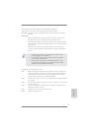
PCIE2 (PCIE x16 slot) is used for PCI Express x16 lane width graphics
cards, or used to install PCI Express graphics cards to support CrossFi-
reX
TM
function.
PCIE4 (PCIE x16 slot) is used for PCI Express x4 lane width cards,
or used to install PCI Express graphics cards to support CrossFireX
TM
function.
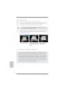
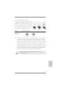
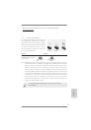
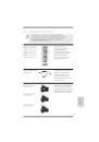
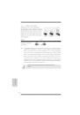
1. In single VGA card mode, it is recommended to install a PCI Ex-
press x16 graphics card on PCIE2 slot.
2. In CrossFireX
TM
mode, please install PCI Express x16 graphics
cards on PCIE2 and PCIE4 slots.
3. Please connect a chassis fan to motherboard chassis fan connec-
tor (CHA_FAN1, CHA_FAN2 or CHA_FAN3) when using multiple
graphics cards for better thermal environment.
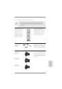
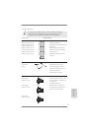
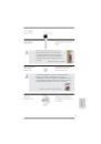
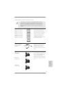
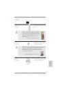
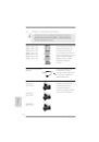
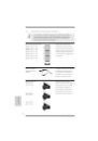
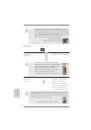
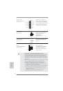
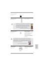
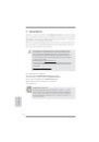
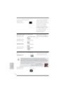
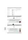
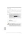
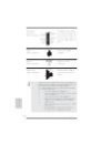
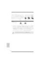
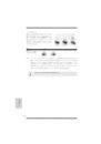
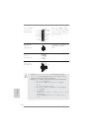
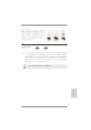
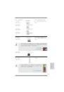
Installing an expansion card
Step 1.
Before installing the expansion card, please make sure that the power
supply is switched off or the power cord is unplugged. Please read the
documentation of the expansion card and make necessary hardware
settings for the card before you start the installation.
Step 2.
Remove the system unit cover (if your motherboard is already installed
in a chassis).
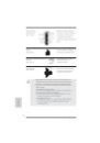
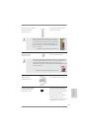
Step 3.
Remove the bracket facing the slot that you intend to use. Keep the
screws for later use.
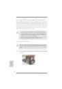
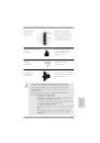
Step 4.
Align the card connector with the slot and press fi rmly until the card is
completely seated on the slot.
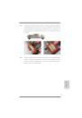
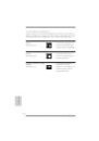
Step 5.
Fasten the card to the chassis with screws.
Step 6.
Replace the system cover.
 1
1
 2
2
 3
3
 4
4
 5
5
 6
6
 7
7
 8
8
 9
9
 10
10
 11
11
 12
12
 13
13
 14
14
 15
15
 16
16
 17
17
 18
18
 19
19
 20
20
 21
21
 22
22
 23
23
 24
24
 25
25
 26
26
 27
27
 28
28
 29
29
 30
30
 31
31
 32
32
 33
33
 34
34
 35
35
 36
36
 37
37
 38
38
 39
39
 40
40
 41
41
 42
42
 43
43
 44
44
 45
45
 46
46
 47
47
 48
48
 49
49
 50
50
 51
51
 52
52
 53
53
 54
54
 55
55
 56
56
 57
57
 58
58
 59
59
 60
60
 61
61
 62
62
 63
63
 64
64
 65
65
 66
66
 67
67
 68
68
 69
69
 70
70
 71
71
 72
72
 73
73
 74
74
 75
75
 76
76
 77
77
 78
78
 79
79
 80
80
 81
81
 82
82
 83
83
 84
84
 85
85
 86
86
 87
87
 88
88
 89
89
 90
90
 91
91
 92
92
 93
93
 94
94
 95
95
 96
96
 97
97
 98
98
 99
99
 100
100
 101
101
 102
102
 103
103
 104
104
 105
105
 106
106
 107
107
 108
108
 109
109
 110
110
 111
111
 112
112
 113
113
 114
114
 115
115
 116
116
 117
117
 118
118
 119
119
 120
120
 121
121
 122
122
 123
123
 124
124
 125
125
 126
126
 127
127
 128
128
 129
129
 130
130
 131
131
 132
132
 133
133
 134
134
 135
135
 136
136
 137
137
 138
138
 139
139
 140
140
 141
141
 142
142
 143
143
 144
144
 145
145
 146
146
 147
147
 148
148
 149
149
 150
150
 151
151
 152
152
 153
153
 154
154
 155
155
 156
156
 157
157
 158
158
 159
159
 160
160
 161
161
 162
162
 163
163
 164
164
 165
165
 166
166
 167
167
 168
168
 169
169
 170
170
 171
171
 172
172
 173
173
 174
174
 175
175
 176
176
 177
177
 178
178
 179
179