14
ASRock H61M-DG3/USB3 Motherboard
English
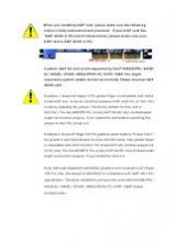
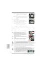
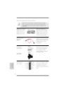
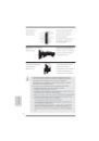
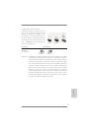
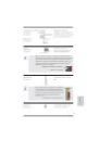
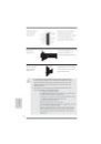
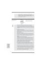
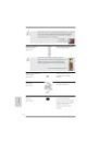
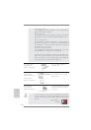
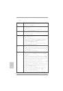
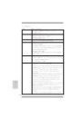
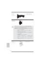
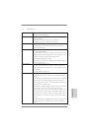
Step 3-3. Carefully place the CPU into the
socket by using a purely vertical mo-
tion.
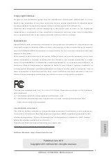
Step 3-4. Verify that the CPU is within the sock-
et and properly mated to the orient
keys.
Step 4. Close the socket:
Step 4-1. Rotate the load plate onto the IHS.
Step 4-2. While pressing down lightly on load
plate, engage the load lever.
Step 4-3. Secure load lever with load plate tab
under retention tab of load lever.
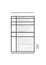
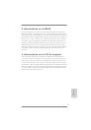
2.2 Installation of CPU Fan and Heatsink
For proper installation, please kindly refer to the instruction manuals of your CPU
fan and heatsink.
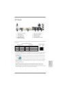
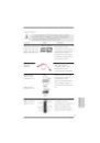
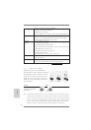
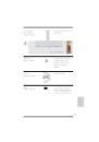
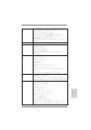
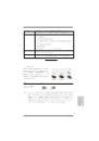
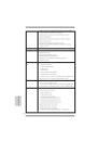
Below is an example to illustrate the installation of the heatsink for 1155-Pin CPU.
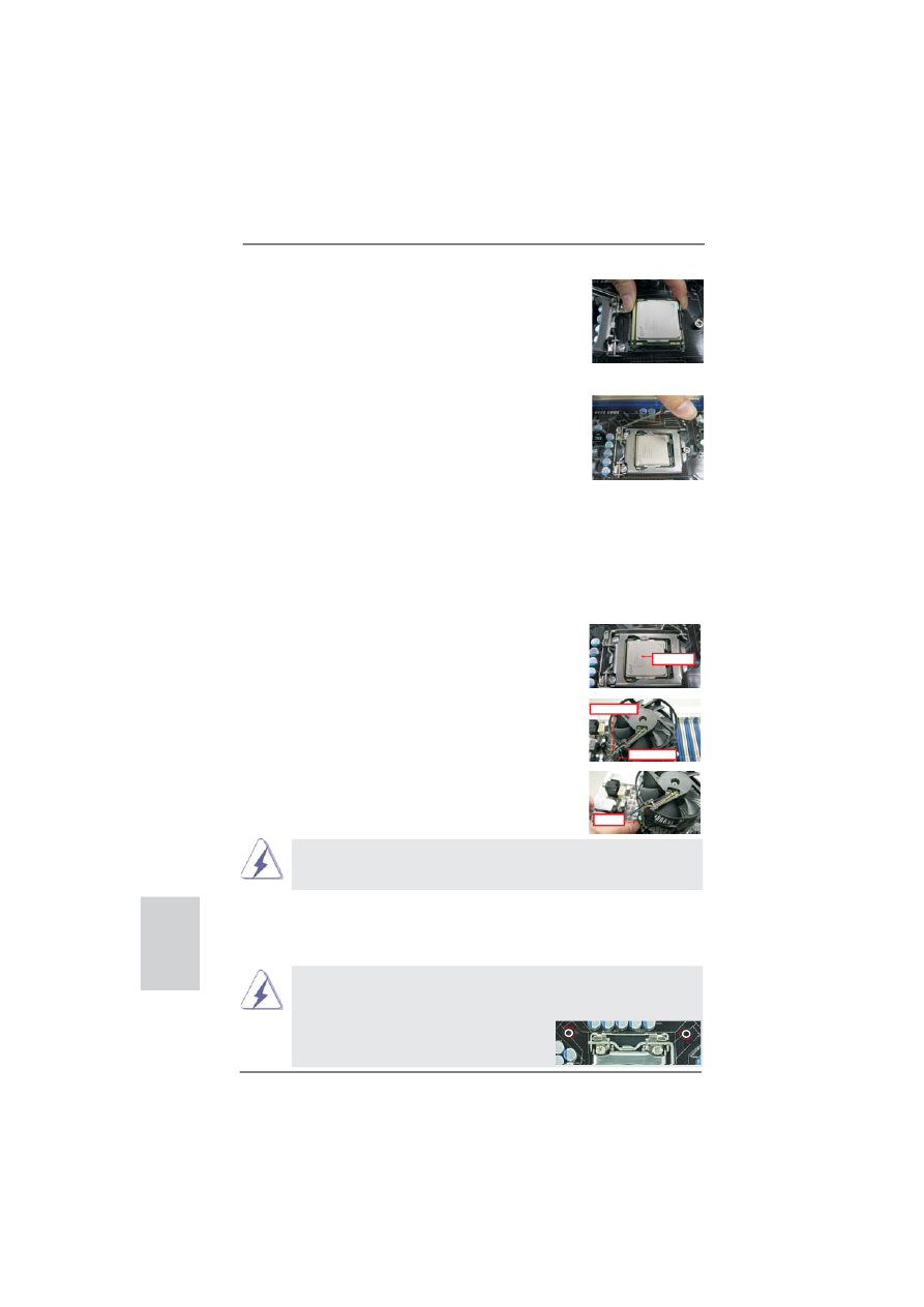
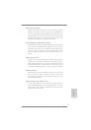
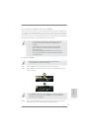
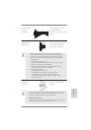
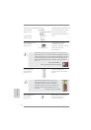
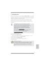
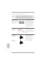
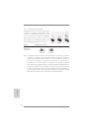
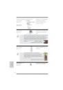
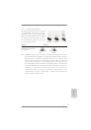
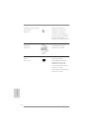
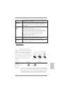
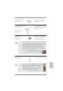
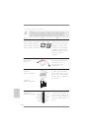
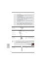
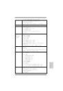
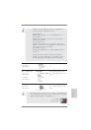
Step 1. Apply thermal interface material onto center of
IHS on the socket surface.
Step 2. Place the heatsink onto the socket. Ensure
fan cables are oriented on side closest to the
CPU fan connector on the motherboard (CPU_
FAN1, see page 2, No. 3).
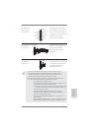
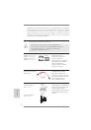
Step 3. Align fasteners with the motherboard through-
holes.
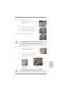
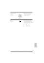
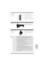
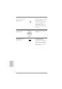
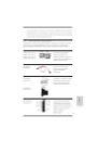
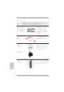
Step 4. Rotate the fastener clockwise, then press
down on fastener caps with thumb to install
and lock. Repeat with remaining fasteners.
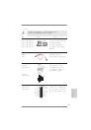
If you press down the fasteners without rotating them clockwise, the
heatsink cannot be secured on the motherboard.
Step 5. Connect fan header with the CPU fan connector on the motherboard.
Step 6. Secure excess cable with tie-wrap to ensure cable does not interfere with
fan operation or contact other components.
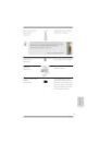
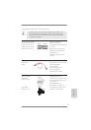
Apply Thermal
Interface Material
Fan cables on side
closest to MB header
Fastener slots
pointing straight out
Press Down
(4 Places)
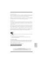
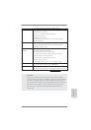
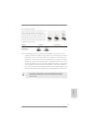
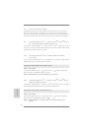
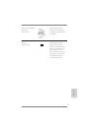
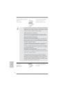
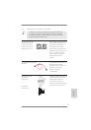
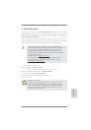
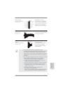
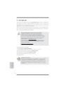
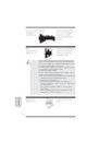
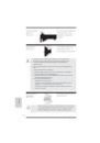
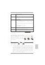
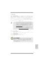
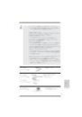
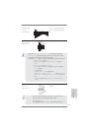
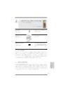
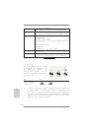
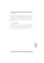
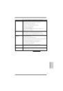
Please be noticed that this motherboard supports Combo Cooler
Option (C.C.O.), which provides the fl exible option to adopt three dif-
ferent CPU cooler types, Socket LGA 775, LGA 1155 and LGA 1156.
The white throughholes are for Socket LGA
1155/1156 CPU fan.
 1
1
 2
2
 3
3
 4
4
 5
5
 6
6
 7
7
 8
8
 9
9
 10
10
 11
11
 12
12
 13
13
 14
14
 15
15
 16
16
 17
17
 18
18
 19
19
 20
20
 21
21
 22
22
 23
23
 24
24
 25
25
 26
26
 27
27
 28
28
 29
29
 30
30
 31
31
 32
32
 33
33
 34
34
 35
35
 36
36
 37
37
 38
38
 39
39
 40
40
 41
41
 42
42
 43
43
 44
44
 45
45
 46
46
 47
47
 48
48
 49
49
 50
50
 51
51
 52
52
 53
53
 54
54
 55
55
 56
56
 57
57
 58
58
 59
59
 60
60
 61
61
 62
62
 63
63
 64
64
 65
65
 66
66
 67
67
 68
68
 69
69
 70
70
 71
71
 72
72
 73
73
 74
74
 75
75
 76
76
 77
77
 78
78
 79
79
 80
80
 81
81
 82
82
 83
83
 84
84
 85
85
 86
86
 87
87
 88
88
 89
89
 90
90
 91
91
 92
92
 93
93
 94
94
 95
95
 96
96
 97
97
 98
98
 99
99
 100
100
 101
101
 102
102
 103
103
 104
104
 105
105
 106
106
 107
107
 108
108
 109
109
 110
110
 111
111
 112
112
 113
113
 114
114
 115
115
 116
116
 117
117
 118
118
 119
119
 120
120
 121
121
 122
122
 123
123
 124
124
 125
125
 126
126
 127
127
 128
128
 129
129
 130
130
 131
131
 132
132
 133
133
 134
134
 135
135
 136
136
 137
137
 138
138