52
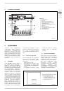
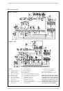
3.1.1
Operating cycle
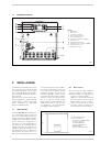
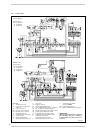
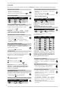
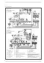
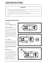
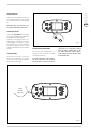
Before igniting the boiler, use a voltmeter to
make sure that the electrical connection to
the terminal block has been made properly,
respecting the position of live and neutral,
as shown in the diagram. Then press the
switch on the control panel detecting volta-
ge and lighting the led lamp.
The boiler is now ready to start working; a
discharge current is sent to the ignition
electrode through the programmer, and the
gas valve opens at the same time.
Burner ignition normally takes place within
2 or 3 seconds. However, it is possible for
ignition failures to occur, with consequent
activation of signal indicating that the equip-
ment has “locked out”.
Failures may be due to one of the following
causes:
–
Gas failure
The control box runs through the cycle
normally sending electric power to the
ignition electrode. The electrode conti-
nues spark discharge for a maximum of
8 and 4 sec. If the burner does not igni-
te, the control box “locks out”.
This may occur upon first ignition or
after long periods of boiler lay-off when
there is air in the pipes. It may be caused
by the failure of the gas valve to open
owing to a break in the electric coil.
.
–
Ignition electrode fails to spark
In the boiler, only opening of gas to the
burner is seen to occur. After 8 and 4
sec. the control cox “locks out”.
This may be due to there being a break
in the wire of the electrode or the wire
not being properly fastened to the termi-
nal of the control box; or else, the tran-
sformer has burnt out.
–
No detection of flame
The continuous spark discharge of the
electrode is noted starting from ignition
even though the burner is lit.
After 8 and 4 seconds have elapsed, the
sparks cease, the burner goes out, and
the warning lamp indicating equipment
“lock-out” lights up.
This occurs when the position of live and
neutral has not been respected on the
terminal block. There is a break in the
wire of the sensing electrode or the elec-
trode itself is earthed: the electrode is
worn out and needs replacing.
The control box is falty
When there is a sudden voltage failure, the
burner shuts out immediately; when power
supply returns, the boiler will start up again
automatically.
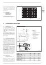
3.1.2
Ionization circuit
The ionization circuit is to be checked using
a dial-type micro-ammeter, or preferably a
digital micro-ammeter with a 0 to 50 µA
scale.
The micro-ammeter terminals must be
series-connected to the wire of the sensing
electrode. Under normal operating condi-
tions, the value oscillates between 6 - 10
µA.
The minimum value of the ionization current
for which the equipment can “lock out” is
about 1 µA.
In this case, make sure that there is a good
electrical contact and check the degree of
wear of the end part of the electrode and
the corresponding ceramic protection.
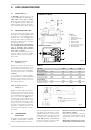
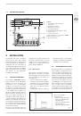
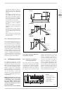
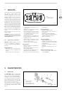
3.2
REGULATION THERMOSTAT
“Slim Power”
boilers are equipped with a
regulating thermostat with a double con-
tact having differentiated setting (6 fig. 2).
This makes it possible to obtain a reduction
of heat output before the burner goes out
completely, by means of the coil assembly
installed on the gas valve regulator.
This step-modulation system affords the fol-
lowing advantages:
– higher overall boiler efficiency;
– containment within acceptable values of
the increase in temperature that takes
place in the cast-iron body (heat inertia)
when the burner goes out.
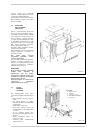
3.3
SMOKE SAFETY DEVICE
This is a safety device against possible
smoke emission into the ambience (8 fig. 2).
The safety device goes into action by
blocking operation of the gas valve when the
return of the smoke into the ambience is
continuous and in quantities that might con-
stitute a danger.
To restart the boiler, the cover of the ther-
mostat must be unscrewed and reset the
underlying button.
Make sure the control panel is disconnec-
ted before carrying out this operation.
Should the boiler continue to “lock out”, it will
be necessary to make a careful check on
the flue pipe, making all the necessary modi-
fications and amendments so that it can
work properly.
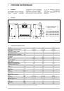
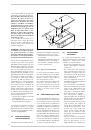
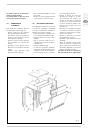
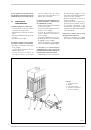
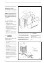
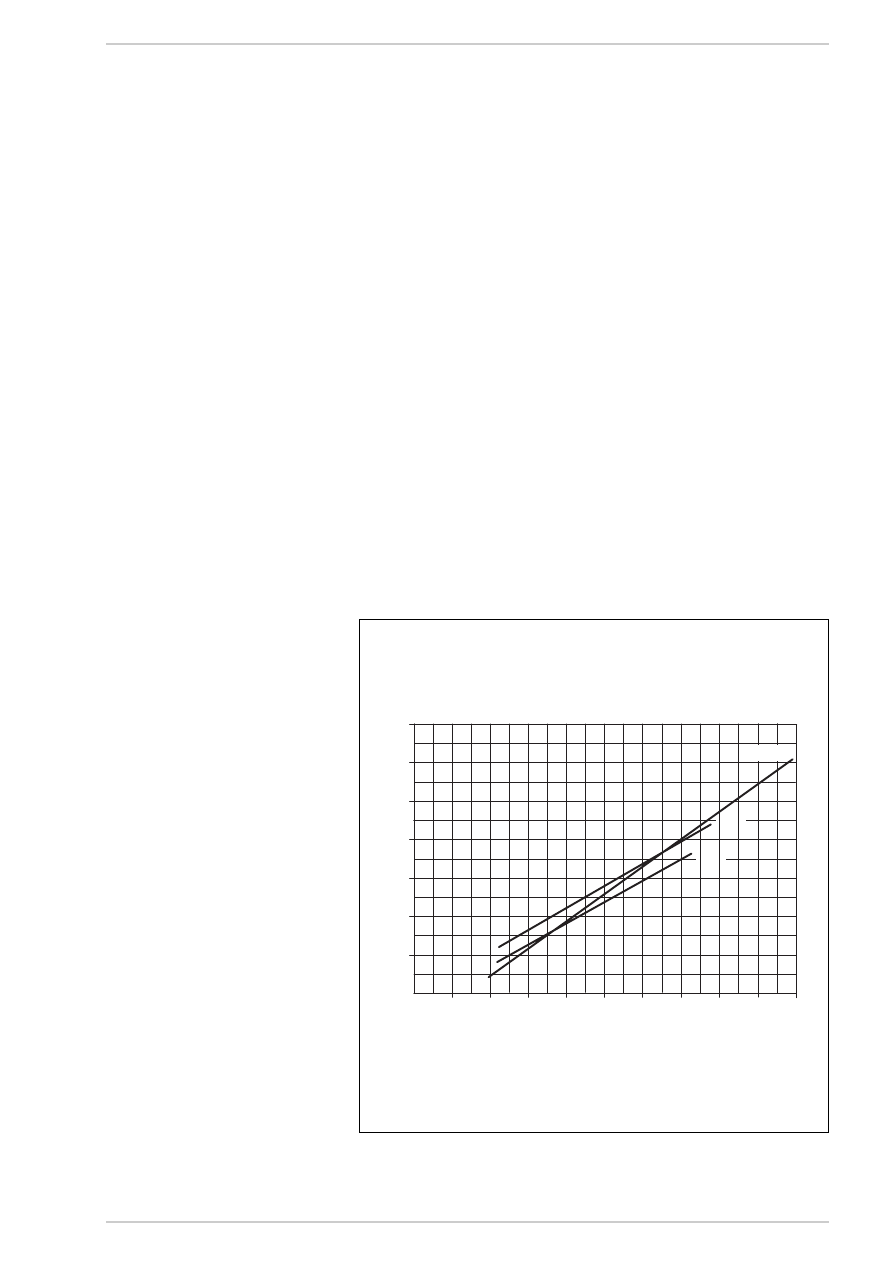
3.5
SYSTEM AVAILABLE HEAD
The head available is shown in graph in fig. 9.
0
120
2.000
9.000
8.000
7.000
6.000
5.000
4.000
3.000
PORTATA (l/h)
PERDIT
A DI C
ARICO (mbar)
100
80
20
40
60
1.80
1.99
140
10.000 11.000
1.110
Fig. 9
FLOW RATE (l/h)
HEAD A
V
AIL
ABLE
(mbar)