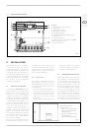
TO TURN ON THE HEATING
– Turn on the main switch.
– Set the correct hour of the day and the day of the week.
– Place in automatic mode with the button
.
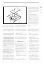
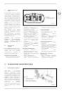
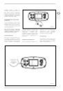
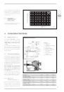
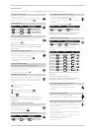
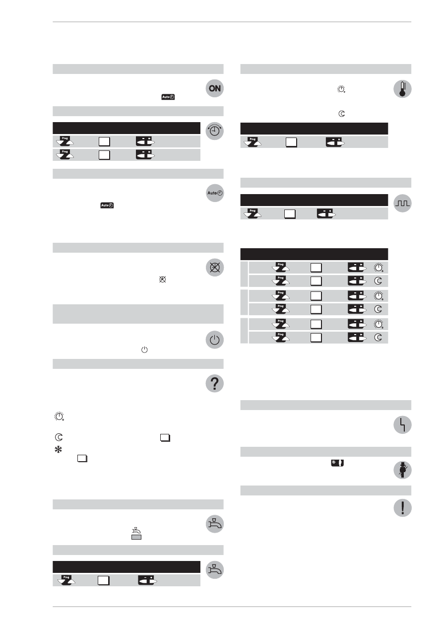
TO SET THE HOUR
HOW TO USE THE AUTOMATIC MODE
In the automatic mode the temperature of the room is regu-
lated on the basis of the periods of heating chosen.
– Push the button
.
NOTE: Select the heating periods according to one’s daily
requirements; in this way it is possible to significantly
save on energy.
TO ACTIVATE CONTINUOUS HEATING
The continuous heating mode keeps the temperature of the
room at the set level via the regulating knob.
– Push the “Continuous Operation” button
.
– Regulate the room temperature with the
regulating knob.
TO SET THE STANDBY MODE
(when the user is away for a long period of time)
The standby mode keeps the temperature of the room at
the level of antifreeze protection.
– Push the “Standby mode” button
.
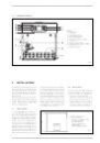
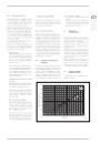
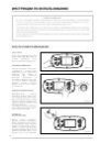
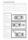
MEANING OF THE SYMBOLS
On the display a few of the symbols indicate the current ope-
rating state. The appearance of a line under one of these
symbols signals that the corresponding operating state is
“active”.
Heating at the nominal temperature
(regulating knob)
Heating at reduced temperature (line
).
Heating at antifrost protection temperature
(line
).
NOTE: For further information on the symbols and the
operating state refer to the detailed description of the
heating plant.
TO VARY THE HOT WATER PRODUCTION
The production of hot water can be activated or deactivated
by the push of a button.
– Push the button “Hot water”
.
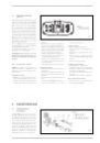
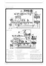
IF THE HOT WATER IS TOO HOT OR TOO COLD
IF THE ROOMS ARE TOO HOT OR TOO COLD
– Check that current operating state on the display.
– In the case of nominal temperature
.
Increase or reduce the temperature of the room with the
regulating knob.
– In the case of reduced temperature
.
NOTE: After each regulation wait at least two hours for
the new temperature to expand through the room.
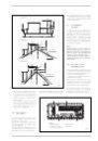
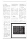
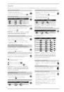
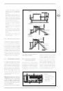
TO CHANGE THE HEATING PERIODS
With reference to the day chosen set the changes
as following:
NOTE: The heating periods automatically repeat on a
weekly basis.
To this end select the automatic mode.
It is possible to reset the standard programme on line 23
by pushing the buttons + and – at the same time.
IF THE HEATING DOES NOT WORK PROPERLY
– Refer to the detailed documentation
on the heating system, following the fault finding
instructions.
TO MEASURE GAS COMBUSTION
– Push the “chimneysweep” button
.
The heating will work according to the level requested.
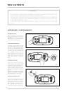
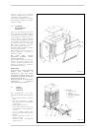
HOW TO SAVE ENERGY WITHOUT FOREGOING ON COMFORT
– A temperature of around 21°C is advised in the rooms
that are used. Every degree above this will increase hea-
ting costs by 6–7%.
– Aerate the rooms only for a brief period, opening the win-
dows completely.
– In the rooms that are not used place the regulating valve
in the antifreeze position.
– Leave the space in front of the radiators free from
obstructions (remove furniture, curtains...).
– Close windows and blinds to reduce
dispersion of heat.
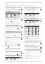
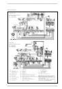
Select the
Display
Set the regulation
line
with the buttons
hour of the day
day of the week
1
2
14
15
Select the
Display
Pre-select the weekly block
line
or the single day
1-7 = week
1 = Lu/7 = Do
5
Period
Push
Display
Set
For
requested
button
hour
°C
Start
End
Start
End
Start
End
6
7
8
9
10
11
Select the
Display
Change the temperature
line
with the buttons
°C
14
P
e
riod 1
P
e
riod 2
P
e
riod 3
13
Select the
Display
Set the desired
line
temperature
°C
58
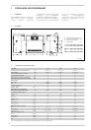
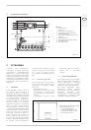
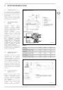
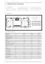
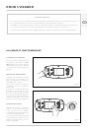
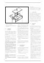
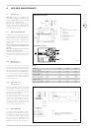
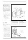
CONTROL SYSTEM
In order to get the highest potential out of the “RVA 43.222” regulator follow the instructions given below: