5
ULTRA-DI PRO DI4000 User Manual
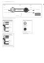
1.3 Control elements
The BEHRINGER ULTRA-DI PRO has four identical channels. The control elements
are identical on all channels.
(6)
(7)
(2)
(4)
(1)
(3)
(5)
Fig. 1.1: Control and display elements on the front panel
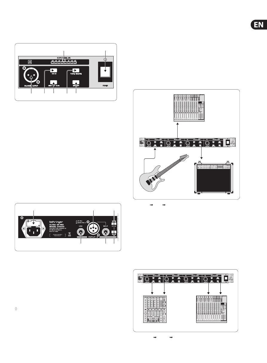
(1)
OUTPUT
. This is the balanced output of the ULTRA-DI PRO. The connection
to the mixing desk should be made with a standard high-quality
balanced cable.
(2)
+20 dB
gain switch for pre-amplification of low level signals.
(3)
Switchable
HIGH CUT
filters (8 kHz) for guitar applications (6 dB/Oct).
(4)
With the
PHASE REVERSE
switch the input signal is reversed in phase
by 180°.
(5)
Use the
GND LIFT
switch to either connect the ground of input and output
or keep them completely separate. Depending on the grounding of the
connected devices linking or disconnecting will reduce hum or prevent
ground loops.
GROUND LIFT
on means no interconnection.
(6)
The
OUTPUT LEVEL
meter displays the output level of the Ultra-DI PRO in a
range from -24 dB to +18 dB.
(7)
Use the
POWER
switch to turn on the BEHRINGER ULTRA-DI PRO.
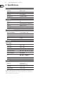
(
11
)
(
12
)
(
13)
(10)
(8)
(9)
Fig. 1.2: Rear panel elements of the BEHRINGER Ultra-DI PRO
(8)
LINK
. This is the unbalanced parallel output of the ULTRA-DI PRO.
Connect this to the input of the backline or monitor amplifier.
(9)
INPUT
. Connect the source to this 1/4" jack to input the signal.
(10)
and
(13)
The
-20 dB ATTENUATION
switches greatly increase the operating
range of the ULTRA-DI PRO. From the low level signals of a high impedance
guitar to the hot speaker terminals of a PA amplifier. Depressing both will
give 40 dB attenuation.
◊
Only use the ‑20 dB switches if you are sure the Ultra‑DI PRO is
clipping (overloading) and not your mic pre‑amp. Always use as little
attenuation as possible to get the best possible signal‑to‑noise ratio.
(11)
FUSE HOLDER/VOLTAGE SELECTOR
. Please make sure that the voltage
indicated on the unit matches your local voltage, before you attempt to
connect and operate the VINTAGER AC112. Blown fuses may only be replaced
by fuses of the same type and rating. Some models allow for inserting the
fuse holder in two different positions, in order to switch over from 230 V
to 115 V operation, and vice versa. Please note that for 115 V operation
outside Europe, you need to use a fuse of a higher rating (see chapter 3
“Installation”). Use the enclosed power cord to connect the unit to the mains.
(12)
To provide maximum flexibility the ULTRA-DI PRO is also fitted with an
unbalanced
XLR INPUT
to connect the source.
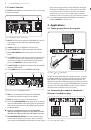
2. Applications
2.1 Tapping signal from a (bass) guitar
Microphone Input
Out
DI4000
In
Link Out
Fig. 2.1: Guitar DI box Guitar Amp/Mixer
This figure shows the standard application of any Direct Inject box. The signal to
the amplifier is unaffected, it is just tapped off to be routed to the microphone
input of the mixer. Especially bass guitars benefit from this application. It is
difficult to find a microphone which handles high level low frequencies well and
with a linear frequency response. Using the ULTRA-DI PRO will give you clean and
crisp sound. Connect the ULTRA-DI PRO after any effects devices, so that their
effect will be heard over the PA system or on the recording.
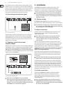
2.2 Converting the output of a keyboard /
DJ-mixer / headphone plug
Out
Out
In
In
Microphone Inputs Pan left and right
Fig. 2.2: DJ-mixer 2 x DI box mixer