5
ULTRALINK PRO MX882 User Manual
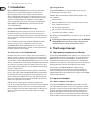
3. Installation
Your BEHRINGER ULTRALINK PRO was carefully packed in the factory and
the packaging was designed to protect the unit from rough handling.
Nevertheless, we recommend that you carefully examine the packaging and its
contents for any signs of physical damage, which may have occurred in transit.
◊
If the unit is damaged, please do not return it to us, but notify your
dealer and the shipping company immediately, otherwise claims for
damage or replacement may not be granted. Shipping claims must be
made by the consignee.
3.1 Rack mounting
The BEHRINGER ULTRALINK PRO fits into one standard 19" rack unit of space
(1 3/4"). Please allow at least an additional 4" depth for the connectors on the
back panel. Be sure that there is enough air space around the unit for cooling
and please do not place the ULTRALINK PRO on high temperature devices such as
power amplifiers etc. to avoid overheating.
3.2 Mains voltage
Before you connect your ULTRALINK PRO to the mains, please make
sure that your local voltage matches the voltage required by the
unit!
The fuse holder on the female mains connector has 3 triangular markers,
with two of these triangles opposing each other. Your ULTRALINK PRO is set to
the operating voltage printed next to these markers, and can be set to another
voltage by turning the fuse holder by 180°.
CAUTION: this instruction
does not apply to export models exclusively designed, e.g. for
115 V operation!
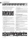
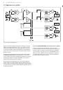
3.3 Audio connections
The audio inputs and outputs on the BEHRINGER ULTRALINK PRO are fully
balanced. If possible, connect the unit to other devices in a balanced
configuration to allow for maximum interference immunity.
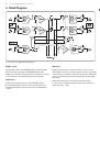
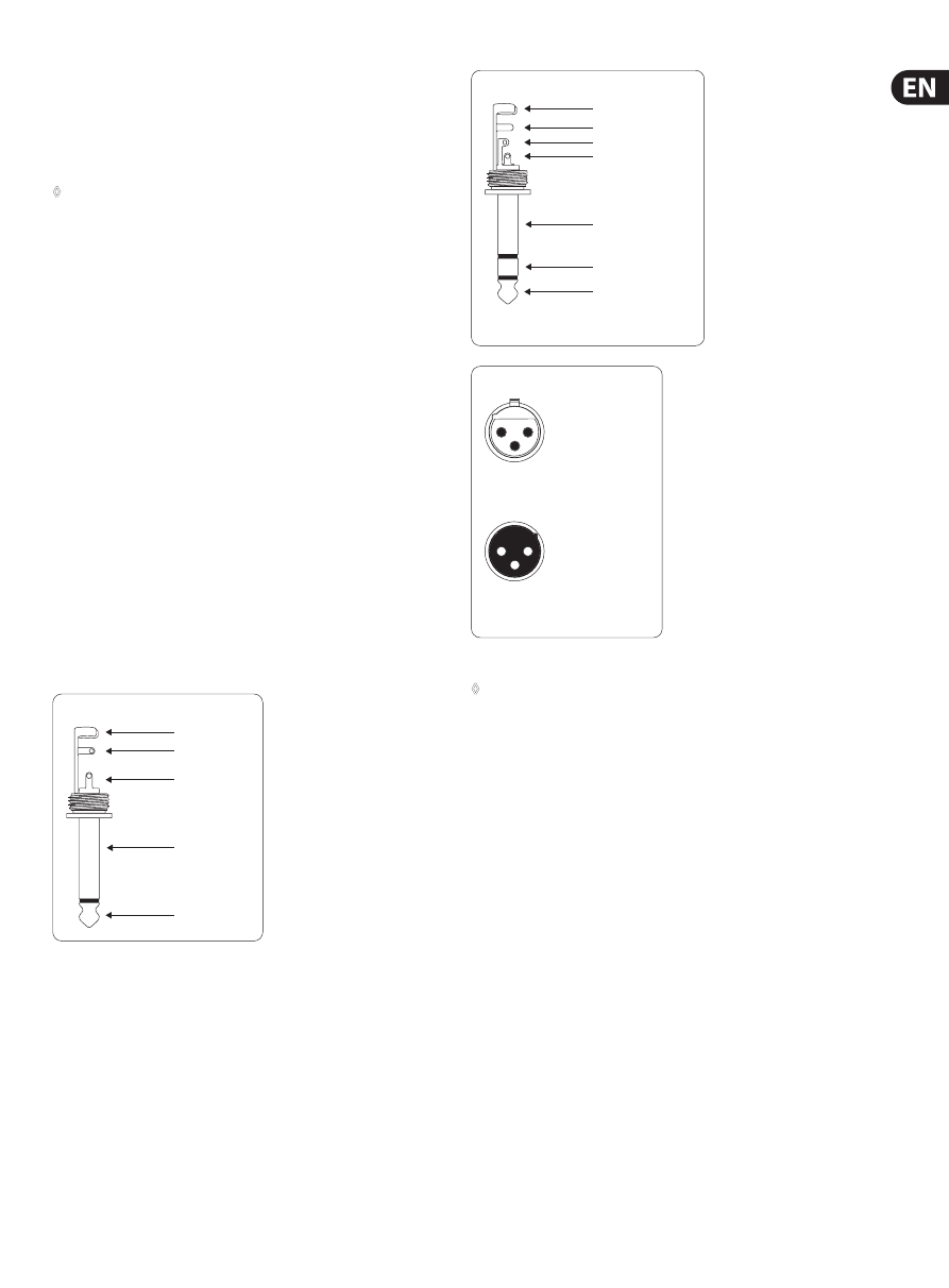
output
For unbalanced use, pin 1 and pin 3
have to be bridged
1 = ground/shield
2 = hot (+ve)
3 = cold (-ve)
input
1
2
3
1
2
3
Balanced use with XLR connectors
Fig. 3.1: Different plug types
◊
Please ensure that only qualified persons install and operate the
ULTRALINK PRO. During installation and operation the user must have
sufficient electrical contact to earth. Electrostatic charges might affect
the operation of the ULTRALINK PRO!
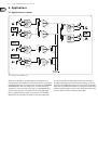
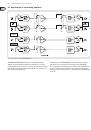
strain relief clamp
sleeve
tip
sleeve
(ground/shield)
Unbalanced ¼" TS connector
tip
(signal)
strain relief clamp
sleeve
ring
tip
sleeve
ground/shield
For connection of balanced and unbalanced plugs,
ring and sleeve have to be bridged at the stereo plug.
Balanced ¼" TRS connector
ring
cold (-ve)
tip
hot (+ve)