6
ULTRALINK PRO MX882 User Manual
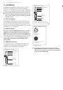
4. Control Elements
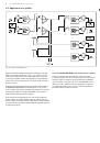
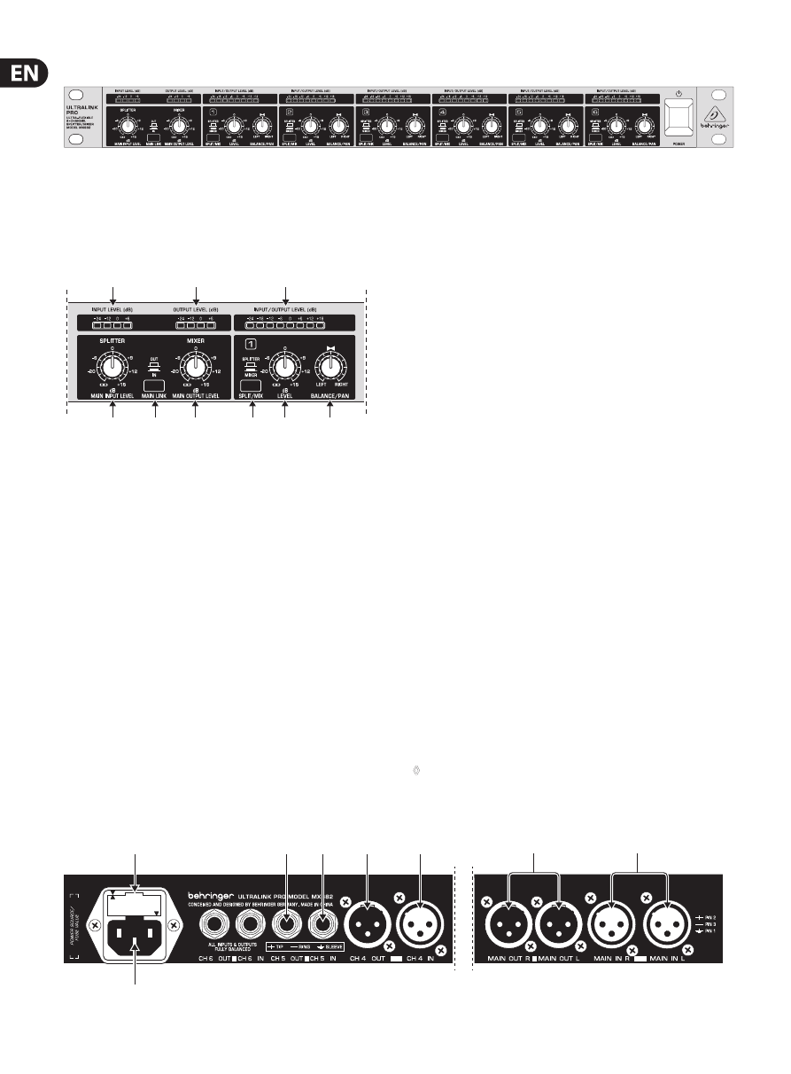
Fig. 4.1: ULTRALINK PRO front panel
The Behringer ULTRALINK PRO has six identical channels. Each channel is
equipped with two rotary controls, one button and eight LEDs. Moreover there is
a main section with two rotary controls, one button and eight LEDs.
4.1 The front panel control elements
(2)
(1)
(3)
(4)
(6)
(7)
(9)
(5)
(8)
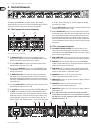
Fig. 4.2: Control elements on the front panel
(1)
The
MAIN INPUT LEVEL
control sets the main input gain, before the
signal reaches the input bus. In SPLIT mode, the MAIN INPUT LEVEL control
determines the common output level for all mono outputs.
(2)
The 4-digit
INPUT LEVEL
meter informs you about the input level of the
main input within a range from -24 to +6 dB.
(3)
By depressing the
MAIN LINK
switch you can route the MAIN INPUT signal
to the MAIN OUT. This way it is possible to route a maximum of eight input
channels to the main mix.
(4)
The
MAIN OUTPUT LEVEL
control adjusts the output level applied to the
main outputs. The levels present at the six mono outputs are not affected.
Summing the signal levels of several mono channels can overload the main
output stage. The MAIN OUTPUT LEVEL control is therefore used to adjust the
overall output level.
(5)
The 4-digit
OUTPUT LEVEL
meter informs you about the output level of the
main input within a range from -24 to +6 dB.
(6)
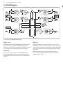
This
SPLIT/MIX
switch sets the respective channel to SPLITTER or MIXER mode.
(7)
The
LEVEL
control determines the signal level of the individual channels.
In SPLIT mode, the LEVEL control sets the output level of the mono channels.
In MIX mode, however, it controls the amount of the mono channel’s input
signal feeding into the main output section; at the same time, the level of
the mono channel can be determined, which—owing to the maximum gain
of +15 dB—allows for converting, e.g., home recording levels (-10 dBV)
into studio levels (+4 dBu).
(8)
The 8-digit
OUTPUT LEVEL
meter informs you about the output level of each
channel within a range from -24 to +18 dB.
(9)
With the
BALANCE/PAN
control you can set the balance between the left
and right main signals. In SPLIT mode, the main input signal is routed to the
mono output, with the BALANCE control determining the balance beween
the left and right main signal portions. In MIX mode, the mono inputs are
mixed and routed via the LEVEL control to the main outputs, with the PAN
controls determining the allocation of the mono inputs to the left and right
main outputs.
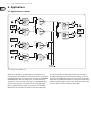
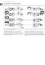
4.2 The rear panel elements
(10)
FUSE HOLDER / VOLTAGE SELECTOR
. Please make sure that your local
voltage matches the voltage indicated on the unit, before you attempt to
connect and operate the ULTRALINK PRO. Blown fuses may only be replaced
by fuses of the same type and rating.
(11)
MAINS CONNECTION
. Use the enclosed power cord to connect the unit to
the mains. Please also note the instructions given in chapter 3 “Installation”.
(12)
MAIN INPUTS
. These are the main audio inputs of your ULTRALINK PRO,
available as balanced XLR connectors. They may feed the mono outputs of all
channels which are operated in SPLIT mode.
(13)
MAIN OUTPUTS
. These are the main outputs, available as balanced XLR
connectors. They may be fed either by the left and right main inputs or by
any of the six mono inputs (or a combination of both).
(14)
MONO INPUTS
(channel 1 to 4). These are the mono inputs.
Connection takes place via balanced XLR connectors.
(15)
MONO OUTPUTS
(channel 1 to 4). These are the mono outputs, available as
balanced XLR connectors.
(16)
MONO INPUTS
(channel 5 to 6). These are the mono inputs.
Connection takes place via balanced phone jacks.
(17)
MONO OUTPUTS
(channel 5 to 6). These are the mono outputs, available as
balanced phone jacks.
◊
Please take the time to fill in and return the warranty card within
14 days after the date of purchase, so as to benefit from our extended
warranty. Or use our online registration option available on the World
Wide Web at behringer.com.
(10)
(17)
(16)
(15)
(14)
(13)
(12)
(11)
Fig. 4.3: Rear panel elements