4
Installation Guide
ASV‑PV (DN 15‑50)
SMT/SI
VI.A1.I7.7O
Heating Solutions
ENGLISH
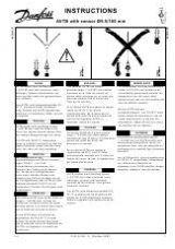
Automatic balancing valves ASV‑PV is used
together with shut‑off and measuring valve
ASV‑M to control the differential pressure
in risers where the radiator valves have
presetting facilities. ASV‑PV is also used
together with adjustment valve ASV‑I to
control the differential pressure and flow
in risers where the radiator valves have no
presetting facilities (P/Q control), fig. ❶.
ASV‑PV maintains constant differential
pressure across the riser.
Max. working pressure ...........................16 bar
Differential pressure across valve:
DN 15 ‑ 40 ...........................................10‑150 kPa
DN 50 .................................................. 10‑250 kPa
Max. flow temperature............................120 °C
Valve size
Internal
thread
External
thread
DN 15
Rp ½
G ¾ A
DN 20
Rp ¾
G 1 A
DN 25
Rp 1
G 1¼ A
DN 32
Rp 1¼
G 1½ A
DN 40
Rp 1½
G 1¾ A
DN 50
‑
G 2½
Impulse line: G 1⁄16
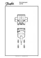
Installation
ASV‑PV must be installed in the return
pipe. The flow must be in the direction of
the arrow on the valve body fig. ❸.
It is recommended that an FV filter be
installed in the system supply pipe. The
impulse tube must be fitted on the flow
pipe, e.g. via an ASV‑I or an ASV‑M valve.
The tube must be flushed through before
being fitted on the + connection of the
ASV‑PV automatic balancing valves fig. ❷.
ASV‑PV must in addition be installed as
determined by installation conditions.
When the system has been in use for
some time, the connections with external
threads should be tightened once again to
minimize the risk for leakage.
Shut‑off
Turning the ASV‑PV knob fully clockwise
will shut‑off the riser fig. ❷ ①.
Pressure testing
Max. test pressure ....................................25 bar
Notes:
When pressure testing you must secure that
both sides of the membrane have the same
static pressure. That means the impulse
tube must be connected and any needle
valves must be open. If ASV‑PV is installed
in combination with ASV‑M both valves can
be open or closed (both valves must be in
the same position!). If ASV‑PV is installed in
combination with ASV‑I both valves must
be open. During this operation (closing or
opening the valves) please make sure that
there is never lower pressure on upper side of
the membrane.
If ASV‑ PV is installed in combination with
ASV‑I do not drain main pipes while leaving
risers under pressure / filled with water. Doing
so ASV‑PV membrane would have lower
pressure on upper side which might damage
the membrane.
If this instructions are ignored, the membrane
of the automatic balancing valve might be
damaged.
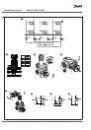
Setting/adjustment
The ASV‑PV valves are sold in four different
∆p setting ranges. The valves are factory–
set to a defined value as described on
Factory presseting table on fig. ❾. Use
the following procedure to set the desired
differential presure: the setting on ASV‑PV
can be changed by turning the setting
spindle fig. ❷②.
Turning the spindle clockwise increases
the setting; turning it counter clockwise
reduces the setting.
If the setting is not known, turn the spindle
fully clockwise. With this the setting on
ASV‑PV is at maximum value within setting
range. Now turn the spindle a number of
times (n) as described in fig. ❾ until the
required differential pressure setting is
obtained.
Note:
Do not turn the spindle more than 20 turns as
it will become disengaged.
The cock (closed, fig. ❹–① ‑ open,
fig. ❹–②) can be used for water tapping
and filling.
Starting
You can fill the system with the drain‑cock
on ASV‑PV. The system shall be ventilated
at the highest point. During system start
– opening the shut‑off on ASV‑PV and
partner valve ‑ please secure that there
is the same static pressure on both sides
or higher pressure on upper side of the
membrane (+ connection, Fig.❷). If filling
is done by opening ASV‑PV and partner
valve, please make sure there is a pressure
on the upper side of the membrane by
opening partner valve first before ASV‑PV
is opened.
Notes!
a) ASV‑PV used with ASV‑M (Fig. ❻):
if this procedure is not followed, the
membrane of ASV‑PV might be damaged.
b) ASV‑PV used with ASV/I (Fig. ❼):
If this procedure is not followed, ASV‑PV
may become locked in closed position
even if the valve is fully opened.
c) Both ASV‑PV and ASV‑M/I should be
always fully opened if used together with
dedicated shut‑off valves (Fig. ❽).
Fault location
Check the following if the riser valve does
not function correctly:
1. Is the flow direction through the valve
correct?
2. Is the impulse tube fitted correctly and
are any needle valves open?
3. Is the valve shut‑off open?
Insulation (DN 15 ‑ 40)
The styropor packaging in which the valve
is supplied can be used as an insulation
jacket for temperatures up to 80 °C.