14
INSTRUCTIONS FOR THE INSTALLER
•
ELECTRIC CONNECTION
The connection to the electric grid must be carried out by qualified personnel and in conformity with the regulations
in force.
The voltage of the electric system must correspond to the value indicated in the label under the appliance. Make
sure that the electric system is provided with an effective ground connection in compliance with the regulations and
provisions of the law.
Grounding is compulsory.
If the appliance is not equipped with a plug, apply a standardized
plug to the power supply cable.
It is possible to effect the connection to the electric grid directly, by interposing an omnipolar switch having a contact
opening distance of at least 3 mm.
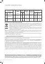
GAS TRANSFORmATIONS AND ADJUSTmENTS
•
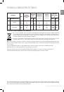
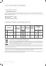
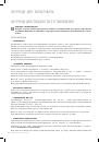
REPLACING THE NOzzLES
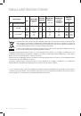
If the equipment is adjusted for a type of gas that is different from the one available, it is necessary to replace the
burner nozzles.
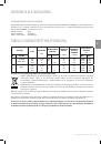
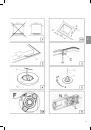
The choice of the nozzles to replace must be made according to the table of the “technical characteristics”.
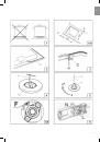
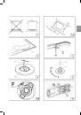
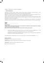
Act as follows:
•
Remove the racks and burners.
•
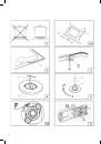
By means of a straight spanner L, unscrew the nozzle U (fig.4) and substitute it with the corresponding one.
•
Tighten the nozzle strongly.
•
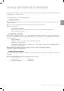
ADJUSTING THE BURNERS
The lowest flame point must always be properly adjusted and the flame must remain on even if there is an abrupt shift
from the maximum to the minimum position.
If this is not so, it is necessary to adjust the lowest flame point as follows:
•
start the burner up;
•
turn the tap up to the minimum position (small flame);
•
remove the knob from the tap rod;
•
introduce a flat-tip screwdriver C in the hole F or near the tap rod (fig.5-5A) and turn the by-pass screw up to
a proper adjustment of the lowest flame point.
As regards G30 gas burners, the by-pass screw must be tightened completely.
mAINTENANCE
•
REPLACING THE POWER SUPPLY CABLE
If the power supply cable should be replaced, it is necessary to use a cable with a section of 3x0.75mm
2
, type
HO5vv-F
or
H05RR-F
, complying with the regulations in force for the hob with gas burners.
The connection to the terminal board must be effected as shown in fig. 6:
brown cable
L
(fase)
blue cable
N
(neutro)
green-yellow cable
(terra)
INSTRUCTIONS FOR THE INSTALLER