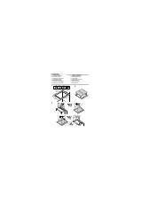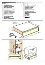
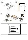
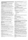
Vorbereitung der Einbaumöbel, Abb. 1/2/3
Einbaumöbel:
Sie müssen bis mindestens 90 °C temperaturbe-
ständig sein.
Ausschnitt:
Späne nach den Ausschnittarbeiten entfernen.
Schnittflächen:
Mit hitzebeständigem Material versiegeln.
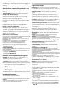
Einbau über einem Schubfach, Abbildung 2a
Im Schubfach befindliche Metallgegenstände können durch den
Rückstrom der Luft, bei der Belüftung des Kochfelds hohe Tem-
peraturen erreichen. Daher wird empfohlen einen Zwischenbo-
den einzubauen.
Zwischenboden: Ein geeignetes Zubehörteil kann über unseren
Kundendienst bezogen werden. Die Artikelnummer für dieses
Zubehörteil lautet 448964.
Arbeitsplatte: Sie muss mindestens 20 mm dick sein.
Der Abstand zwischen dem oberen Bereich der Arbeitsplatte
und dem oberen Bereich des Schubfachs muss 65 mm betra-
gen.
Montage über einem Backofen, Abbildung 2b
Ablage: Muss über eine Mindestdicke von 30 mm verfügen.
Hinweis:
Schlagen Sie in der Montageanleitung für den Back-
ofen nach, falls der Abstand zwischen Kochfeld und Backofen
vergrößert werden muss.
Belüftung: Der Abstand zwischen Backofen und Kochfeld muss
mindestens 5 mm betragen.
Einbau über dem Geschirrspüler
Es muss ein Zubehörteil dazwischen eingebaut werden. Zube-
hörteile erhalten Sie bei unserem Kundendienst. Die Artikelnum-
mer für dieses Zubehörteil lautet 448964.
Arbeitsplatte: Sie muss mindestens 20 mm und darf höchstens
40 mm dick sein.
Es muss folgender Abstand zwischen dem oberen Bereich der
Arbeitsplatte und dem oberen Bereich des Geschirrspülers ein-
gehalten werden:
■
60 mm bei Einbau über einem Kompakt-Geschirrspüler.
■
65 mm bei Einbau über einem normalen Geschirrspüler.
Gebläse, Abbildung 3
Für die Lüftung des Kochfelds ist Folgendes notwendig:
■
Eine Öffnung im oberen Bereich der Rückwand des Möbels
(Abb. 3a)
.
■
Ein Abstand zwischen der Rückwand des Möbels und der
Küchenwand
(Abb. 3b)
.
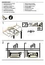
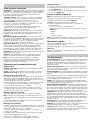
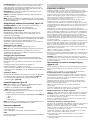
Einbau des Geräts, Abb. 4/5
Hinweis:
Zum Einbauen des Kochfeldes Schutzhandschuhe ver-
wenden. Die nicht sichtbaren Flächen können scharfe Kanten
aufweisen.
1.
Die mitgelieferten Verankerungen einbauen
(Abb. 4)
.
Hinweis:
Keine elektrischen Schraubendreher verwenden.
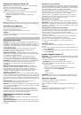
2.
Das Gerät ans Stromnetz anschließen und auf ordnungsge-
mäßen Betrieb überprüfen.
– Hinweise zur elektrischen Spannung siehe Typenschild.
– Nur nach dem Anschlussplan anschließen
(Abb. 5)
.
1. Braun
2. Blau
3. Gelb und grün
Hinweis:
Je nach Anschlussart muss eventuell die Anordnung
der vom Werk gelieferten Klemmen verändert werden.
Ausbau des Geräts
Das Gerät von der Stromzufuhr trennen.
Die Halterungen entfernen.
Entnehmen Sie das Kochfeld, indem Sie von unten dagegen
drücken.
Achtung!
Schäden am Gerät! Versuchen Sie nicht, das Gerät durch
Hebeln von oben zu entnehmen.
en
Ú
Installation instructions
Important notes
Safety:
Safety in use is only guaranteed if the technical
installation of the hob has been carried out correctly and in
accordance with the assembly instructions. The installation
technician shall be liable for any damage caused as a result of
unsuitable installation.
Electric connection:
Only by an authorised specialist
technician. The guidelines set out by the local electricity provider
must be observed.
Type of connection:
The appliance falls under protection class I
and can only be used in combination with a grounding
conductor connection.
The manufacturer accepts no responsibility for any malfunction
or damage caused by incorrect electrical installations.
Installation:
The appliance must be connected to a fixed
installation and the means of disconnecting it from the fixed
installation must be installed according to the installation
instructions.
Built-in assembly under worktop:
The induction hobs may only
be installed over a drawer, ovens with forced ventilation from the
same brand and dishwashers from the same brand.
Refrigerators, unventilated ovens and washing machines may
not be installed beneath the hob.
Power cable:
Do not tie the power cable or pass it along sharp
edges. If there is an oven installed below, pass the cable along
the rear corners of the oven to the connection box. It must be
positioned so that it does not touch any of the hot parts of the
hob or the oven.
Hob:
flat, horizontal, stable. Follow the hob manufacturer's
instructions.
Warranty:
an unsuitable installation, connection or assembly will
invalidate the product warranty.
Note:
Any change to the appliance's interior, including changing
the power cable, must only be performed by specially trained
members of the Technical Assistance Service.
Preparation of assembly units, figures 1/2/3
Built-in kitchen units:
Minimum temperature resistance of
90°C.
Gap:
Remove any shavings after performing cutting work.
Cut surfaces:
Seal with heat resistant material.
Assembly over drawer, figure 2a
Metal objects stored inside the drawer could become very hot
due to the air recirculating from the hob ventilation system. If
this occurs, an intermediate support is recommended.
Intermediate support: An appropriate accessory can be
obtained from our Technical Assistance Service. The reference
code for this accessory is 448964.
Worktop: Must have a minimum thickness of 20 mm.
The distance between the top of the working surface and the top
of the drawer must be 65 mm.
Assembly over oven, figure 2b
Hob: must have a minimum thickness of 30 mm.
Note:
If the distance between the hob and oven must be
increased, refer to the installation instructions for the oven.
Ventilation: The distance between the oven and the hob must be
at least 5 mm.
Installation above the dishwasher
An intermediate accessory must be installed. The accessory
may be ordered from our Technical Assistance Service. The
reference code for this accessory is 448964.
Worktop: Must have a minimum thickness of 20 mm and
maximum thickness of 40 mm.
The space between the top of the working surface and the top
of the dishwasher must be:
■
60 mm if installed over a compact dishwasher.
■
65 mm if installed over a full-size dishwasher.
Ventilation, figure 3
Ventilating the hob requires:
■
an opening on the upper part of the kitchen unit's rear wall
(figure 3a)
.
■
a separation between the rear part of the kitchen unit and
kitchen wall
(figure 3b)
.

Document Outline
- Û Instrucciones de montaje
- Observaciones importantes
- Seguridad: la seguridad durante el uso sólo está garantizada si la instalación se ha efectuado de manera correcta en el aspecto técnico y en conformidad con estas instrucciones de montaje. Los daños causados por un montaje inadecuado serán resp...
- Conexión eléctrica: sólo a cargo de un técnico especialista autorizado. Se tendrá que regir por las disposiciones de la compañía abastecedora de electricidad de la zona.
- Tipo de conexión: el aparato pertenece a la clase de protección I y sólo puede utilizarse en combinación con una conexión con conductor de toma a tierra.
- El fabricante no se hace responsable del funcionamiento inadecuado y de los posibles daños motivados por instalaciones eléctricas no adecuadas.
- Instalación: el aparato debe ser conectado a una instalación fija y deben ser incorporados medios de desconexión a la instalación fija de acuerdo a las reglamentaciones de la instalación.
- Montaje empotrado bajo encimera: las placas de inducción sólo pueden ser instaladas sobre cajón, hornos con ventilación forzada de la misma marca o lavavajillas de la misma marca. Debajo de la placa de cocción no se pueden instalar frigoríficos...
- Cable de alimentación: no aprisionar el cable de alimentación ni pasarlo por bordes afilados. Si hay un horno montado debajo, pasar el cable por las esquinas traseras del horno hasta la caja de conexión. Debe colocarse de manera que no toque parte...
- Encimera: plana, horizontal, estable. Siga las instrucciones del fabricante de la encimera.
- Garantía: una instalación, conexión o montaje inadecuado supone la pérdida de validez de la garantía del producto.
- Preparación de los muebles de montaje, figuras 1/2/3
- Muebles empotrados: resistentes a una temperatura de 90°C como mínimo.
- Hueco: retirar las virutas después de los trabajos de corte.
- Montaje sobre el cajón, figura 2a
- Los objetos metálicos que se encuentren en el cajón podrían alcanzar temperaturas elevadas debido a la recirculación del aire procedente de la ventilación de la placa, si esto ocurre, se recomienda utilizar un soporte intermedio.
- Soporte intermedio: se puede adquirir un accesorio adecuado en nuestro Servicio de Asistencia Técnica. El código de referencia de este accesorio es el 448964.
- Encimera: debe tener como mínimo un grosor de 20 mm.
- La distancia entre la parte superior de la encimera y la parte superior del cajón debe ser de 65 mm.
- Montaje sobre horno, figura 2b
- Montaje sobre lavavajillas
- Se debe instalar un accesorio intermedio. El accesorio se debe solicitar a nuestro Servicio de Asistencia Técnica. El código de referencia de este accesorio es el 448964.
- Encimera: debe tener un grosor de 20 mm como mínimo y 40 mm como máximo.
- La distancia entre la parte superior de la encimera y la parte superior del lavavajillas debe ser de:
- Ventilación, figura 3
- Instalar el aparato, figuras 4/5
- Desmontar el aparato
- Desconectar el aparato de la red eléctrica.
- Quitar los anclajes de sujeción.
- Extraer la placa de cocción ejerciendo presión desde abajo.
- Sicherheitshinweis: Die Sicherheit beim Gebrauch des Gerätes ist nur gewährleistet, wenn der Einbau technisch korrekt und gemäß dieser Montageanleitung vorgenommen wurde. Für Schäden, die durch einen unsachgemäßen Einbau entstehen, haftet der...
- Elektrischer Anschluss: Er muss von einem konzessionierten Fachmann vorgenommen werden. Dabei gelten die Bestimmungen der örtlichen Stromversorger.
- Anschlusstypen: Das Gerät gehört zur Schutzklasse I und darf nur in Kombination mit einem geerdeten Anschluss verwendet werden.
- Der Hersteller übernimmt keine Verantwortung für Betriebsstörungen oder mögliche Schäden die auf eine fehlerhafte elektrische Installation zurückzuführen sind.
- Einbau: Das Gerät muss fest angeschlossen werden und es müssen beim festen Anschluss gemäß den Montagevorschriften Trennungsmöglichkeiten vorhanden sein.
- Einbau unter der Arbeitsplatte: Induktionskochfelder dürfen nur über Schubfächern, Backöfen mit Gebläse desselben Herstellers oder Geschirrspülern desselben Herstellers eingebaut werden. Unter dem Kochfeld dürfen keine Kühlschränke, Backöfe...
- Netzkabel: Das Netzkabel nicht einklemmen oder über scharfe Kanten führen. Wenn sich unter dem Kochfeld ein Backofen befindet, das Kabel über die hinteren Kanten des Backofens bis zur Anschlussdose führen. Das Netzkabel muss so angebracht werden,...
- Arbeitsplatte: Sie muss eben, horizontal und stabil sein. Die Anweisungen des Arbeitsplatten-Herstellers beachten.
- Garantie: Ein unsachgemäßer Einbau, Anschluss oder eine fehlerhafte Montage führen zum Verlust der Garantie.
- Vorbereitung der Einbaumöbel, Abb. 1/2/3
- Einbaumöbel: Sie müssen bis mindestens 90 °C temperaturbeständig sein.
- Ausschnitt: Späne nach den Ausschnittarbeiten entfernen.
- Einbau über einem Schubfach, Abbildung 2a
- Im Schubfach befindliche Metallgegenstände können durch den Rückstrom der Luft, bei der Belüftung des Kochfelds hohe Temperaturen erreichen. Daher wird empfohlen einen Zwischenboden einzubauen.
- Zwischenboden: Ein geeignetes Zubehörteil kann über unseren Kundendienst bezogen werden. Die Artikelnummer für dieses Zubehörteil lautet 448964.
- Arbeitsplatte: Sie muss mindestens 20 mm dick sein.
- Der Abstand zwischen dem oberen Bereich der Arbeitsplatte und dem oberen Bereich des Schubfachs muss 65 mm betragen.
- Montage über einem Backofen, Abbildung 2b
- Einbau über dem Geschirrspüler
- Es muss ein Zubehörteil dazwischen eingebaut werden. Zubehörteile erhalten Sie bei unserem Kundendienst. Die Artikelnummer für dieses Zubehörteil lautet 448964.
- Arbeitsplatte: Sie muss mindestens 20 mm und darf höchstens 40 mm dick sein.
- Es muss folgender Abstand zwischen dem oberen Bereich der Arbeitsplatte und dem oberen Bereich des Geschirrspülers eingehalten werden:
- Gebläse, Abbildung 3
- Einbau des Geräts, Abb. 4/5
- Ausbau des Geräts
- Das Gerät von der Stromzufuhr trennen.
- Die Halterungen entfernen.
- Entnehmen Sie das Kochfeld, indem Sie von unten dagegen drücken.
- Safety: Safety in use is only guaranteed if the technical installation of the hob has been carried out correctly and in accordance with the assembly instructions. The installation technician shall be liable for any damage caused as a result of unsuit...
- Electric connection: Only by an authorised specialist technician. The guidelines set out by the local electricity provider must be observed.
- Type of connection: The appliance falls under protection class I and can only be used in combination with a grounding conductor connection.
- The manufacturer accepts no responsibility for any malfunction or damage caused by incorrect electrical installations.
- Installation: The appliance must be connected to a fixed installation and the means of disconnecting it from the fixed installation must be installed according to the installation instructions.
- Built-in assembly under worktop: The induction hobs may only be installed over a drawer, ovens with forced ventilation from the same brand and dishwashers from the same brand. Refrigerators, unventilated ovens and washing machines may not be installe...
- Power cable: Do not tie the power cable or pass it along sharp edges. If there is an oven installed below, pass the cable along the rear corners of the oven to the connection box. It must be positioned so that it does not touch any of the hot parts o...
- Hob: flat, horizontal, stable. Follow the hob manufacturer's instructions.
- Warranty: an unsuitable installation, connection or assembly will invalidate the product warranty.
- Preparation of assembly units, figures 1/2/3
- Built-in kitchen units: Minimum temperature resistance of 90°C.
- Gap: Remove any shavings after performing cutting work.
- Assembly over drawer, figure 2a
- Metal objects stored inside the drawer could become very hot due to the air recirculating from the hob ventilation system. If this occurs, an intermediate support is recommended.
- Intermediate support: An appropriate accessory can be obtained from our Technical Assistance Service. The reference code for this accessory is 448964.
- Worktop: Must have a minimum thickness of 20 mm.
- The distance between the top of the working surface and the top of the drawer must be 65 mm.
- Assembly over oven, figure 2b
- Installation above the dishwasher
- An intermediate accessory must be installed. The accessory may be ordered from our Technical Assistance Service. The reference code for this accessory is 448964.
- Worktop: Must have a minimum thickness of 20 mm and maximum thickness of 40 mm.
- The space between the top of the working surface and the top of the dishwasher must be:
- Ventilation, figure 3
- Installing the appliance, figures 4/5
- Uninstalling the appliance
- Disconnect the appliance from the mains.
- Remove the anchoring devices.
- Push the hob upwards from below to remove it.
- Sécurité : la sécurité pendant l'utilisation n'est garantie que si l'installation a été effectuée de manière correcte du point de vue technique et conformément à ces instructions de montage. L'installateur sera responsable de tout dommage p...
- Connexion électrique : ne peut être effectuée que par un spécialiste autorisé. Il devra suivre les dispositions du fournisseur d'électricité dans la zone.
- Type de branchement : l'appareil fait partie de la classe de protection I et ne peut être utilisé qu'avec une prise possédant un conducteur de prise de terre.
- Le fabricant se dégage de toute responsabilité quant au fonctionnement inapproprié et aux possibles dommages provoqués par des installations électriques non appropriées.
- Installation : l'appareil doit être connecté à une installation fixe et des moyens de déconnexion doivent être prévus sur l'installation fixe, conformément aux réglementations de l'installation.
- Montage encastré sous le plan de travail : les plaques à induction ne peuvent être installées que sur tiroir, des fours avec ventilation forcée de la même marque ou des lave- vaisselle de la même marque. Sous la plaque de cuisson, il n'est pas...
- Câble d'alimentation : ne pas coincer le câble d'alimentation, ne pas le faire passer sur des arêtes vives. S'il y a un four déjà monté en dessous, faire passer le câble par les coins arrière du four jusqu'au boîtier de connexion. Il doit ê...
- Plan de travail : plat, horizontal, stable. Respectez les instructions du fabricant du plan de travail.
- Garantie : une mauvaise installation, un mauvais branchement ou un montage inadapté peuvent conduire à la perte de validité de la garantie du produit.
- Préparation des meubles de montage, figures 1/2/3
- Meubles encastrés : capables de résister à une température d'au moins 90 °C.
- Creux d'encastrement : retirer les copeaux dus à la découpe.
- Montage sur tiroir, schéma 2a
- Les objets métalliques qui se trouvent dans le tiroir pourraient atteindre des températures élevées en raison de la recirculation de l'air provenant de la ventilation de la plaque, c'est pourquoi il est recommandé d'utiliser un support interméd...
- Support intermédiaire : il est possible d'acheter un accessoire approprié auprès de notre service d'assistance technique. Le code de référence de cet accessoire est le 448964.
- Plan de travail : son épaisseur minimum doit être de 20 mm.
- La distance entre la partie supérieure du plan de travail et la partie supérieure du tiroir doit être de 65 mm.
- Montage sur four, schéma 2b
- Encastrement au-dessus d'un lave-vaisselle
- Un accessoire intermédiaire doit être installé. Celui-ci doit être demandé auprès de notre service d'assistance technique. Le code de référence de cet accessoire est le 448964.
- Plan de travail : son épaisseur doit être de 20 mm minimum et de 40 mm maximum.
- La distance entre la partie supérieure du plan de travail et la partie supérieure du lave-vaisselle doit être de :
- Ventilation, figure 3
- Installer l'appareil, figures 4/5
- Démonter l'appareil.
- Débrancher l'appareil du réseau électrique.
- Ôter les fixations de support.
- Extraire la table de cuisson en exerçant une pression depuis le bas.
- â Istruzioni per il montaggio
- Indicazioni importanti
- Sicurezza: la sicurezza durante l'uso è garantita solo se l'installazione è stata effettuata in modo corretto dal punto di vista tecnico e in conformità con le presenti istruzioni per il montaggio. I danni causati da un montaggio inadeguato sarann...
- Collegamento elettrico: può essere effettuato solo da un tecnico specializzato autorizzato. È opportuno rispettare le disposizioni della società di fornitura di energia elettrica locale.
- Tipo di collegamento: l'apparecchio appartiene alla classe di protezione I e può essere utilizzato esclusivamente in combinazione con una connessione dotata di conduttore di messa a terra.
- Il fabbricante non è responsabile del funzionamento inadeguato e dei possibili danni causati da installazioni elettriche non adeguate.
- Installazione: l'apparecchio deve essere collegato a una rete fissa e devono essere installati dispositivi di interruzione dell'alimentazione di rete, conformemente alle pertinenti regolamentazioni.
- Montaggio ad incasso sotto il piano di lavoro: le piastre a induzione possono essere installate esclusivamente sopra cassetti, forni a ventilazione forzata della stessa marca, o lavastoviglie della stessa marca. Non è possibile installare sotto il p...
- Cavo di alimentazione: non bloccare il cavo di alimentazione né farlo passare lungo bordi taglienti. Nel caso in cui sotto il piano di cottura sia montato un forno, far passare il cavo dagli angoli posteriori del forno fino alla scatola di collegame...
- Piano di lavoro: piatto, orizzontale e stabile. Attenersi alle istruzioni del fabbricante del piano di lavoro.
- Garanzia: la garanzia del prodotto non è valida se l'installazione, la connessione o il montaggio vengono effettuati in maniera impropria.
- Preparazione dei mobili per il montaggio, figure 1/2/3
- Mobili ad incasso: resistenti a una temperatura minima di 90°C.
- Foro: rimuovere i trucioli dopo le operazioni di taglio.
- Montaggio sopra il cassetto, figura 2a
- Gli oggetti metallici che si trovano nel cassetto potrebbero raggiungere temperature elevate a causa del ricircolo dell'aria proveniente dalla ventilazione del piano; si raccomanda, quindi, di utilizzare un supporto intermedio.
- Supporto intermedio: si può acquistare un accessorio adeguato presso il nostro servizio di assistenza tecnica. Il codice di riferimento di questo accessorio è 448964.
- Il piano di lavoro: deve avere uno spessore minimo di 20 mm.
- La distanza tra la parte superiore del piano di lavoro e la parte superiore del cassetto deve essere di 65 mm.
- Montaggio su forno, figura 2b
- Montaggio sopra una lavastoviglie
- È necessario installare un accessorio intermedio. Tale accessorio dovrà essere richiesto al nostro servizio di assistenza tecnica. Il codice di riferimento di questo accessorio è 448964.
- Il piano di lavoro: deve avere uno spessore minimo di 20 mm e massimo di 40 mm.
- La distanza tra la parte superiore del piano di lavoro e la parte superiore della lavastoviglie deve essere di:
- Ventilazione, figura 3
- Installare l'apparecchio, figure 4/5
- Smontare l'apparecchio
- Scollegare l'apparecchio dalla rete elettrica.
- Togliere i dispositivi di fissaggio.
- Estrarre il piano di cottura premendo dal basso.
- Veiligheid: de veiligheid gedurende het gebruik is alleen gegarandeerd indien de montage in technisch opzicht op correcte wijze en in overeenstemming met dit installatievoorschrift uitgevoerd is. De installateur is aansprakelijk voor schade veroorzaa...
- Elektrische aansluiting: deze mag alleen worden uitgevoerd door een bevoegd vakman. Deze wordt geregeld door de voorschriften van de elektriciteitsmaatschappij van de zone.
- Type aansluiting: het apparaat behoort tot beschermingsklasse I en mag alleen worden gebruikt in combinatie met een aansluiting met aardgeleiding.
- De fabrikant is niet aansprakelijk voor de ongeschikte werking en de mogelijke schade veroorzaakt door ongeschikte elektrische installaties.
- Installatie: het apparaat moet worden aangesloten op een vaste installatie waarin middelen voor uitschakeling zijn ingebouwd, in overeenstemming met de reglementeringen van de installatie.
- Montage ingebouwd onder het werkblad: inductieplaten mogen alleen worden geïnstalleerd op een lade, ovens met gedwongen ventilatie van hetzelfde merk of vaatwassers van hetzelfde merk. Onder de kookplaat mogen geen koelkasten, ovens zonder ventilati...
- Voedingskabel: zorg ervoor dat de voedingskabel niet bekneld raakt of langs scherpe randen loopt. Indien er een oven onder gemonteerd is, laat de kabel dan via de achterste hoeken van de oven tot de aansluitkast lopen. Hij moet zo geplaatst worden da...
- Werkblad: vlak, horizontaal, stabiel. Volg de instructies van de fabrikant van het werkblad op.
- Garantie: een ongeschikte installatie, aansluiting of montage houdt het verlies van de geldigheid van de garantie van het product in.
- Gereed maken van de meubels waarin het apparaat wordt gemonteerd, afbeeldingen 1/2/3
- Inbouwmeubelen: ten minste bestand tegen een temperatuur van 90°C.
- Vrije ruimte: verwijder de spaanders na de snijwerkzaamheden.
- Montage op de lade, afbeelding 2a
- Metalen voorwerpen die zich in de lade bevinden kunnen hoge temperaturen bereiken, wat te wijten is aan luchtcirculatie afkomstig van de ventilatie van de plaat. Als dit gebeurt is het raadzaam om een tussensteun te gebruiken.
- Tussensteun: een geschikt accessoire is verkrijgbaar bij onze Technische Dienst. De referentiecode van dit accessoire is 448964.
- Werkblad: moet een dikte hebben van ten minste 20 mm.
- De afstand tussen de bovenzijde van de kookplaat en de bovenzijde van de lade moet 65 mm bedragen.
- Montage op een oven, afbeelding 2b
- Inbouw boven de vaatwasmachine
- Er moet een tussenliggend accessoire geïnstalleerd worden. Dit accessoire moet bij onze technische dienst besteld worden. De referentiecode van dit accessoire is 448964.
- Werkblad: moet een dikte hebben van ten minste 20 mm en maximaal 40 mm.
- De afstand tussen de bovenzijde van de kookplaat en de bovenzijde van de vaatwasmachine moet bedragen:
- Ventilatie, afbeelding 3
- Installeren van het apparaat, afbeeldingen 4/5
- Het apparaat demonteren
- Sluit het apparaat af van het verdeelnet.
- Verwijder de verankeringen.
- Neem de kookplaat uit door van beneden af druk uit te oefenen.
- Sikkerhed: sikkerhed under brug kan kun garanteres, hvis installationen er udført på en korrekt teknisk måde og i overensstemmelse med monteringsinstruktionerne. Skader, der opstår pga. forkert montering, er installatørens ansvar.
- Elektrisk tilslutning: må kun foretages af en uddannet elektriker. Regulativerne fra elforsyningsselskabet i området skal følges.
- Tilslutningstype: apparatet tilhører beskyttelsesklasse I og må udelukkende anvendes sammen med en tilslutning med jordforbindelse.
- Fabrikanten frasiger sig ethvert ansvar for forkert funktion og mulige skader, der skyldes forkert elektrisk installation.
- Installation: apparatet skal sluttes til en fastgjort installation, og der skal monteres afbrydere i overensstemmelse med bestemmelserne for installationen.
- Fastmontering under bordpladen: induktionskomfurer kan kun installeres over skuffer,·varmluftsovne af samme mærke eller opvaskemaskiner af samme mærke. Under kogesektionen kan man ikke installere køleskabe, ovne uden ventilation eller vaskemaskiner.
- Forsyningskabel: sørg for, at forsyningskablet ikke bliver spærret inde eller ført over skarpe kanter. Hvis ovnen er undermonteret, skal du føre kablet på hjørnerne bag på ovnen og frem til tilslutningsboksen. Skal anbringes, så det ikke ber...
- Bordplade: plan, vandret, stabil. Følg bordpladefabrikantens anvisninger.
- Garanti: en forkert installation, tilslutning eller montering betyder, at produktgarantien bortfalder.
- Forberedelse af monteringsmøblerne, figur 1/2/3
- Møbler med udskæringer: modstandsdygtige over for temperaturer op til min. 90°C.
- Udskæring: fjern spånerne, når udskæringsarbejdet er udført.
- Montering over en skuffe, figur 2a
- De metalobjekter, der befinder sig i skuffen, kan opnå høje temperaturer på grund af recirkulationsluften fra kogesektionens ventilation. Derfor anbefales det at bruge en adskillelsesanordning.
- Støtte: Man kan erhverve sig et velegnet stykke ekstraudstyr hos vores serviceafdeling. Referencenummeret til dette ekstraudstyr el 448964.
- Bordplade: skal have en tykkelse på min. 20 mm.
- Afstanden mellem toppen af bordpladen og toppen af skuffen skal være 65 mm.
- Montering over en ovn (figur 2b)
- Montage over en opvaskemaskine
- Ventilation, figur 3
- Installation af apparatet, figur 4/5
- Afmontering af apparatet
- Afbryd apparatets strømtilslutning.
- Fjern forankringerne til fastgørelse.
- Løft kogesektionen op ved at presse nedefra.
- Segurança: a segurança durante a utilização só está garantida se a instalação tiver sido efectuada de forma correcta, a nível técnico, e de acordo com estas instruções de montagem. Os danos causados por uma montagem inadequada serão da r...
- Ligação eléctrica: deve ser efectuada apenas por um técnico especialista autorizado e de acordo com as disposições da companhia de fornecimento eléctrico da zona.
- Tipo de ligação: o aparelho pertence à classe de protecção I e apenas pode ser utilizado em combinação com uma ligação com condutor de tomada de terra.
- O fabricante não se responsabiliza pelo funcionamento incorrecto e por possíveis danos provocados por instalações eléctricas inadequadas.
- Instalação: deve ligar o aparelho a uma instalação fixa e incorporar meios de desconexão na instalação fixa, de acordo com as regulamentações da instalação.
- Montagem dos móveis encastrados por baixo da bancada: só é possível instalar as placas de indução sobre fornos com ventilação forçada da mesma marca. Debaixo da placa de cozedura não se podem instalar frigoríficos, fornos sem ventilação ...
- Cabo de alimentação: não prender o cabo de alimentação, nem passá-lo por extremidades afiadas. Se existir um forno montado por baixo, passar o cabo pelos cantos posteriores do forno até à caixa de derivação. Deve ser colocado de forma a nã...
- Bancada: plana, horizontal, estável. Siga as instruções do fabricante da bancada.
- Garantia: uma instalação, ligação ou montagem inadequada implica a anulação da garantia do produto.
- Preparação dos móveis de montagem, figuras 1/2/3
- Móveis encastrados: resistentes a uma temperatura mínima de 90 °C.
- Cavidade: remover as aparas de madeira após os trabalhos de corte.
- Montagem sobre a gaveta (figura 2a)
- Os objectos metálicos que se encontram no interior da gaveta poderão atingir temperaturas elevadas devido à recirculação do ar proveniente da ventilação da placa. Se tal acontecer, recomenda-se a utilização de um suporte intermédio.
- Suporte intermédio: pode ser adquirido um acessório adequado no nosso Serviço de Assistência Técnica. O código de referência deste acessório é 448964.
- Bancada: deve ter uma espessura mínima de 20 mm.
- A distância entre a parte superior da bancada e a parte superior da gaveta deve ser de 65 mm.
- Montagem sobre o forno (figura 2b)
- Montagem por cima da máquina de lavar loiça
- Deve instalar-se um acessório intermédio. Deve solicitar o acessório ao nosso Serviço de Assistência Técnica. O código de referência deste acessório é o 448964.
- Bancada: deve ter uma espessura de 20 mm, no mínimo, e 40 mm, no máximo.
- A distância entre a parte superior da bancada e a parte superior da máquina de lavar loiça deve ser de:
- Ventilação, figura 3
- Instalar o aparelho, figuras 4/5
- Desmontar o aparelho
- Desligar o aparelho da rede eléctrica.
- Retirar as fixações.
- Retirar a placa de cozedura, exercendo pressão a partir de baixo.
- Sikkerhet: sikker bruk kan bare garanteres dersom montering av apparatet er teknisk korrekt utført og i henhold til monteringsveiledningen. Installatøren er ansvarlig for skader som skyldes feilaktig montering.
- Elektrisk tilkobling: må kun utføres av en kvalifisert tekniker. Den lokale strømleverandørs retningslinjer skal følges.
- Type tilkobling: apparatet tilhører beskyttelsesklasse I og må kun brukes sammen med en jordet stikkontakt.
- Produsenten står ikke ansvarlig for feil bruk og eventuelle skader grunnet uegnede elektriske installasjoner.
- Installasjon: apparatet må kobles til en fast installasjon, og innretninger for å koble fra apparatet må festes til den faste installasjonen i henhold til gjeldende installasjonsregler.
- Fastmontasje under koketoppen: induksjonstoppene kan kun installeres over skuff, ovner med ventilasjonsvifte av samme merke, eller oppvaskmaskiner av samme merke. Under koketoppen kan det ikke monteres kjøleskap, ovner uten ventilasjonsvifte eller v...
- Strømledningen: ikke klem strømledningen, og ikke legg den over skarpe kanter. Hvis det er en ovn montert under, skal ledningen trekkes på hjørnene på baksiden av ovnen og til koblingsboksen. Den må strekkes slik at den ikke berører de varme d...
- Benkeplate: flat, vannrett og stabil. Følg instruksjonene fra produsenten av koketoppen.
- Garanti: en feilaktig installasjon, tilkobling eller montasje vil annullere garantien.
- Klargjøring av møblene for montering, figur 1/2/3
- Innebygde møbler: må tåle en temperatur på minst 90 °C.
- Hulrommet: fjern alle spon etter utskjæringen.
- Montasje over skuffen, figur 2a
- Metallobjekter i skuffen kan bli svært varme på grunn av ventilasjonsluften fra koketoppen. Hvis dette skjer, bør det installeres et mellomlegg.
- Mellomlegg: Du kan skaffe et passende tilbehør fra vår tekniske serviceavdeling. Dette tilbehøret har referansekode el 448964.
- Benkeplate: må ha en minste tykkelse på 20 mm.
- Avstanden mellom oversiden av koketoppen og oversiden av skuffen må være minst 65 mm.
- Montasje over ovn, figur 2b
- Innbygging over oppvaskmaskin
- Ventilasjon, figur 3
- Installere apparatet, figur 4/5
- Demontere apparatet
- Koble apparatet fra strømnettet.
- Fjern klemfestene.
- Trykk koketoppen nedover når du skal løfte den av.
- Ασφάλεια: η ασφάλεια κατά τη χρήση εξασφαλίζεται μόνο εάν η εγκατάσταση έγινε με σωστό τρόπο σε τεχνικό επίπεδο και σύμφωνα με τις οδηγί...
- Σύνδεση στο ηλεκτρικό ρεύμα: μόνο υπ' ευθύνη ενός εγκεκριμένου ειδικού τεχνικού. Θα πρέπει να διέπεται από τους κανόνες της εταιρείας πα...
- Τύπος σύνδεσης στο ηλεκτρικό ρεύμα: η συσκευή ανήκει στην κλάση προστασίας I και μπορεί να χρησιμοποιηθεί μόνο σε συνδυασμό με μία σύνδε...
- Ο κατασκευαστής δεν φέρει ευθύνη για τη μη σωστή λειτουργία και τις πιθανές ζημιές που προκλήθηκαν λόγω μη σωστής ηλεκτρικής εγκατάστασ...
- Εγκατάσταση: η συσκευή πρέπει να συνδέεται σε μια μόνιμη εγκατάσταση και πρέπει να προσαρμόζονται μέσα αποσύνδεσης στη μόνιμη εγκατάστ...
- Εντοιχισμένη συναρμολόγηση κάτω από τον πάγκο: η εγκατάσταση για τις επαγωγικές βάσεις εστιών μπορεί να γίνει μόνο πάνω σε συρτάρι, φούρ...
- Καλώδιο τροφοδοσίας: μη σφηνώνετε το καλώδιο τροφοδοσίας και μην το περνάτε από αιχμηρές άκρες. Αν υπάρχει από κάτω κάποιος φούρνος, περ...
- Πάγκος κουζίνας: επίπεδος, οριζόντιος, σταθερός. Ακολουθήστε τις οδηγίες του κατασκευαστή του πάγκου.
- Εγγύηση: μια μη σωστή εγκατάσταση, σύνδεση στο ηλεκτρικό ρεύμα ή συναρμολόγηση συνεπάγεται την απώλεια ισχύος της εγγυήσεως του προϊόντ...
- Προετοιμασία των επίπλων συναρμολόγησης, σχήματα 1/2/3
- Εντοιχισμένα έπιπλα: ανθεκτικά σε θερμοκρασία 90°C τουλάχιστον.
- Κενός χώρος: απομακρύνετε τα ροκανίδια μετά από τις εργασίες κοπής.
- Συναρμολόγηση πάνω στο συρτάρι, σχήμα 2a
- Τα μεταλλικά αντικείμενα που βρίσκονται στο συρτάρι μπορεί να υπερθερμανθούν λόγω της ανακύκλωσης του αέρα που οφείλεται στον εξαερισμ...
- Ενδιάμεσο χώρισμα: μπορείτε να προμηθευτείτε ένα κατάλληλο εξάρτημα από το Τεχνικό μας Σέρβις. Ο κώδικας αναφοράς για αυτό το εξάρτημα ε...
- Πάγκος κουζίνας: θα πρέπει να έχει πάχος τουλάχιστον 20 χιλιοστών.
- Η απόσταση ανάμεσα στο επάνω μέρος του πάγκου και στο επάνω μέρος του συρταριού θα πρέπει να είναι 65 χιλιοστά.
- Συναρμολόγηση πάνω σε φούρνο, σχήμα 2b
- Τοποθέτηση πάνω από το πλυντήριο πιάτων
- Θα πρέπει να εγκατασταθεί ένα ενδιάμεσο εξάρτημα. Θα πρέπει να ζητήσετε το εξάρτημα από το Τεχνικό μας Σέρβις. Ο κώδικας αναφοράς για αυτ...
- Πάγκος κουζίνας: το πάχος του θα πρέπει να είναι από 20 χιλιοστά το ελάχιστο έως 40 χιλιοστά το μέγιστο.
- Η απόσταση μεταξύ του πάνω μέρους του πάγκου και του πάνω μέρους του πλυντηρίου πιάτων πρέπει να είναι:
- Εξαερισμός, σχήμα 3
- Εγκατάσταση της συσκευής, σχήματα 4/5
- Αποσυναρμολόγηση της συσκευής
- Αποσυνδέστε τη συσκευή από το ηλεκτρικό ρεύμα.
- Αφαιρέστε τα άγκιστρα συγκράτησης.
- Αφαιρέστε τη βάση εστιών ασκώντας πίεση από κάτω.
- Säkerhet: säkerheten vid användning garanteras under förutsättning att installationen har utförts korrekt och i enlighet med denna monteringsanvisning. Skador orsakade av felaktig montering är montörens ansvar.
- Elanslutning: får endast utföras av en behörig fackman. Föreskrifterna från den lokala elleverantören skall följas.
- Anslutningstyp: apparaten tillhör skyddsklass I och får endast användas med en jordad anslutning.
- Tillverkaren tar inget ansvar för felaktig funktion eller skador orsakade av felaktig elinstallation.
- Montering: apparaten ska anslutas till en fast installation som måste innehålla frånkopplingsanordningar för den fasta installationen i enlighet med gällande installationsbestämmelser.
- Inbyggnad under bänkskiva: induktionshällar kan endast installeras över lådor, ugnar med forcerad ventilation av samma märke samt diskmaskiner av samma märke. Under spishällen kan du inte installera kylskåp, ugnar utan ventilation eller tvät...
- Strömförsörjningskabel: kläm inte fast strömförsörjningskabeln och lägg den inte över vassa kanter. Om det finns en ugn monterad under hällen bör du lägga kabeln kring ugnens bakre hörn och därifrån vidare mot väggkontakten. Placera d...
- Bänkskiva: plan, vågrät, stabil. Följ instruktionerna från bänkskivans tillverkare.
- Garanti: vid felaktig montering eller anslutning gäller inte produktgarantin.
- Förberedelse av köksmöblerna för installation, bild 1/2/3
- Inbyggda skåp: tål temperaturer på upp till 90 °C.
- Utrymme: avlägsna sågspånen efter urskärningsarbetet.
- Montering på låda, bild 2a
- Metallföremål som finns i lådan kan bli mycket varma pga. luften som cirkulerar i hällens ventilationssystem. Om detta sker är det lämpligt att placera ett skydd däremellan.
- Mellanskydd: du kan beställa ett lämpligt tillbehör via vår Kundtjänst. Artikelnumret för detta tillbehör el448964 .
- Bänkskiva: den bör ha en tjocklek på minst 20 mm.
- Avståndet mellan bänkskivans övre del och lådans övre del ska vara 65 mm.
- Montering över ugn, bild 2b
- Inbyggnad över diskmaskin
- Ventilation, bild 3
- Installera apparaten, bild 4/5
- Demontera apparaten
- Koppla bort apparaten från elnätet.
- Ta bort stöden.
- Lyft ut hällen genom att trycka underifrån.
- Turvallisuus: käyttöturvallisuus on taattu ainoastaan silloin, kun asennus on suoritettu teknisesti oikein ja näiden asennusohjeiden mukaan. Virheellisestä asennuksesta aiheutuvat vahingot ovat asentajan vastuulla.
- Sähköliitäntä: liitännän saa suorittaa vain valtuutettu alan asiantuntija. Kytkennässä on noudatettava paikallisen sähköntoimittajan sääntöjä.
- Liitäntätyyppi: laitteen suojausluokka on I ja sitä voidaan käyttää vain maadoitetulla sähköliitännällä.
- Valmistaja ei ota vastuuta virheellisestä toiminnasta ja mahdollisista vahingoista, jotka aiheutuvat virheellisistä sähköasennuksista.
- Asennus: Laite on on asennettava kiinteään asennukseen ja kiinteässä asennuksessa on oltava virran katkaisuvälineet asennusta koskevien määräyksien mukaisesti.
- Asentaminen kalusteeseen työtason alapuolelle: induktiokeittotasot voidaan asentaa vain laatikon, samanmerkkisen kiertoilmauunin tai samanmerkkisen astianpesukoneen yläpuolelle. Keittotason alapuolelle ei saa asentaa jääkaappia, tuuletuksella var...
- Virtajohto: virtajohto ei saa jäädä puristuksiin eikä sitä saa viedä terävien reunojen yli. Jos alapuolelle on asennettu uuni, vie johto uunin takanurkkien kautta kytkentärasiaan. Virtajohto on asetettava niin, ettei se koske keittotason tai ...
- Keittotaso: tasainen, vaakasuora, vakaa. Noudata keittotason valmistajan ohjeita.
- Takuu: virheellinen asennus tai liitäntä mitätöi tuotteen takuun.
- Asennuskalusteiden valmisteleminen, kuvat 1/2/3
- Sisäänrakennetut kalusteet: kestävät vähintään 90 °C lämpötilan.
- Asennusaukko: poista lastut leikkaustoimenpiteiden jälkeen.
- Laatikon päälle asentaminen, kuva 2a
- Laatikossa olevat metalliset esineet voivat kuumentua huomattavasti keittotason tuuletuksesta aiheutuvan ilmankierron vuoksi, tällöin on suositeltavaa käyttää välikappaletta.
- Välikappale: sopiva lisävaruste voidaan tilata teknisestä huoltopalvelusta. Tämän lisävarusteen viitekoodi on 448964.
- Työtaso: paksuuden on oltava vähintään 20 mm.
- Keittotason yläreunan ja laatikon yläreunan väliin on jätettävä 65 mm tilaa.
- Asentaminen uunin yläpuolelle, kuva 2b
- Asennus astianpesukoneen yläpuolelle
- Tuuletus, kuva 3
- Laitteen asennus, kuvat 4/5
- Laitteen purkaminen
- Irrota laite sähköverkosta.
- Poista kiinnitysosat.
- Poista keittotaso painamalla sitä alhaalta päin.
- Bezpieczeństwo: bezpieczeństwo podczas użytkowania zapewnione jest wyłącznie w przypadku, gdy urządzenie zostało zainstalowane poprawnie pod względem technicznym i zgodnie z niniejszą instrukcją montażu. Za szkody powstałe w wyniku nieodp...
- Podłączenie elektryczne: powierzać wyłącznie upoważnionemu technikowi specjaliście. Należy przestrzegać rozporządzeń miejscowej firmy dostarczającej energię elektryczną.
- Rodzaj podłączenia: urządzenie posiada stopień ochrony I i można go używać wyłącznie z uziemionym przyłączem.
- Producent nie ponosi odpowiedzialności za niewłaściwe funkcjonowanie urządzenia i ewentualne szkody spowodowane przez niewłaściwą instalację elektryczną.
- Instalacja: urządzenie powinno być podłączone do instalacji stałej, w której należy zastosować odłączniki od instalacji stałej, zgodnie z normami dotyczącymi instalacji.
- Montaż w zabudowie pod blatem: płyty indukcyjne mogą być instalowane wyłącznie na szafkach, piekarnikach z systemem wymuszonej wentylacji tej samej marki lub na zmywarkach do naczyń tej samej marki. Pod płytą kuchenki nie mogą być instalow...
- Kabel zasilania: nie zaciskać kabla zasilania ani nie przeprowadzać go przy ostrych brzegach. Jeśli poniżej zamontowany jest piekarnik, przeprowadzić kabel przy tylnych rogach piekarnika aż do puszki przyłączeniowej. Kabel zasilania należy u...
- Blat: płaski, poziomy, stabilny. Postępować zgodnie ze wskazówkami producenta blatu.
- Gwarancja: nieprawidłowo wykonana instalacja, podłączenie lub montaż powoduje utratę ważności gwarancji produktu.
- Przygotowanie mebli do montażu, rysunki 1/2/3
- Meble w zabudowie: odporne na temperaturę minimum 90°C.
- Otwór: usunąć wióry po wykonaniu wycięcia.
- Montaż na szafce, rysunek 2a
- Jeśli płyta została zainstalowana na szafce, wówczas przedmioty metalowe znajdujące się w szafce mogą nagrzać się do wysokiej temperatury z powodu recyrkulacji powietrza wypływającego z systemu wentylacji płyty. W tym przypadku, zaleca si...
- Podpora przedzielająca: można nabyć odpowiednie akcesorium w naszym Serwisie Technicznym. Kod referencyjny opisywanego akcesorium to 448964.
- Blat: powinien mieć grubość minimum 20 mm.
- Odstęp między górną częścią zabudowy, a górną częścią szafki powinien wynosić 65 mm.
- Montaż na piekarniku, rysunek 2b
- Montaż nad zmywarką do naczyń
- Należy zamontować akcesorium przedzielające. To akcesorium można zamówić w naszym Serwisie Technicznym. Kod referencyjny opisywanego akcesorium: 448964.
- Blat: powinien mieć grubość minimum 20 mm i maksimum 40 mm.
- Odstęp między górną częścią zabudowy i górną częścią zmywarki do naczyń powinien wynosić:
- Wentylacja, rysunek 3
- Instalacja urządzenia, rysunki 4/5
- Demontaż urządzenia
- Odłączyć urządzenie od sieci elektrycznej.
- Usunąć zaczepy mocujące.
- Wyjąć płytę kuchenki, wypychając ją od dołu.
- Güvenlik: kullanım esnasında güvenlik sadece tesis işleminin teknik açıdan doğru ve montaj talimatlarına uygun bir şekilde yapılmış olması durumunda garanti edilmektedir. Uygun şekilde yapılmayan montajdan kaynaklanan hasarlar montaj...
- Elektrik bağlantısı: sadece yetkili bir uzman teknisyenin sorumluluğunda. Daha sonra bölgenizdeki elektrik tedarik şirketinin izni ile yönetilir.
- Bağlantı tipi: aygıt, koruma sınıfı I'ya aittir ve sadece topraklama bağlantısı ile kombinasyon halinde kullanılabilir.
- Üretici, yanlış kullanımdan ve uygun olmayan elektrik kurulumlarından kaynaklanan hasarlardan sorumlu olmayacaktır.
- Kurulum: cihaz, sabit bir tesisata bağlanmalı ve bağlantı sökme araçları, montaj yönergelerine uygun olarak sabit tesisata dahil edilmelidir.
- Tezgah altı gömme montaj: indüksiyon plakaları yalnızca aynı markalı motorlu havalandırması olan fırınlar üzerine kurulabilir. Pişirme tezgahının altına buzdolabı, havalandırmasız fırın veya çamaşır makinesi kurulamaz.
- Besleme kablosu: besleme kablosunu sıkıştırmayınız ve keskin kenarların üzerinden geçirmeyiniz. Aşağıda monte edilmiş bir fırın varsa, kabloyu fırının arka köşelerinden bağlantı kutusuna kadar geçiriniz. Pişirme tezgahı veya ...
- Tezgah: düz, yatay, stabil. Tezgahın üretici talimatlarını izleyiniz.
- Garanti: yanlış kurulum, bağlantı ya da montaj, ürünün garantisinin geçerliliğini yitirmesine yol açacaktır.
- Montaj mobilyalarının hazırlanması, şekil 1/2/3
- Gömme mobilyalar: en az 90°C ısıya dayanıklıdırlar.
- Girinti: kesme işlerinden sonra talaşları temizleyiniz.
- Çekmecenin üzerinde montaj, şekil 2a
- Çekmecenin içinde bulunan metal objeler, tezgah havalandırmasından kaynaklanan hava sirkülasyonundan dolayı yüksek ısıya maruz kalabilir. Bu olursa, bir ara destek kullanılması tavsiye edilir.
- Ara destek: Teknik Destek Servisimizden uygun bir aksesuar talep edebilirsiniz. Bu aksesuarın referans kodu 448964'tür.
- Tezgah: en az 20 mm kalınlığa sahip olmalıdır.
- Tezgahın üst kısmıyla çekmecenin üst kısmı arasındaki mesafe 65 mm olmalıdır.
- Fırın üzerine montaj, şekil 2b
- Bulaşık makinesi üzerine montaj
- Havalandırma, şekil 3
- Cihazı takınız, şekil 4/5
- Cihazı sökünüz
- Cihazın elektrik bağlantısını kesiniz.
- Tespit bağlantılarını çıkarınız.
- Pişirme tezgahını çıkarmak için aşağıdan baskı uygulayınız.
- Техника безопасности: Безопасная эксплуатация прибора гарантируется только в том случае, если его установка и подключение к электросет...
- Подключение к электросети: должно производиться только аттестованным специалистом. При этом необходимо придерживаться инструкций мес...
- Вид подключения: данный прибор соответствует классу защиты I и может использоваться только при условии наличия заземления.
- Производитель не несет ответственности за некорректную работу прибора и возможные повреждения, вызванные неправильно проведенным под...
- Установка: Необходимо подключить прибор к стационарной электропроводке и предусмотреть средства отключения от электросети, согласно с...
- Установка встраиваемой варочной панели в столешницу: Индукционные варочные панели можно устанавливать только над духовыми шкафами с п...
- Кабель питания: следите, чтобы кабель питания не был зажат или касался острых кромок. В случае установки варочной панели над духовым шка...
- Столешница: плоская, горизонтальная, устойчивая. Следуйте инструкциям производителя столешницы.
- Гарантия: неправильная установка, подключение или монтаж влекут за собой отмену гарантии производителя.
- Подготовка мебели к установке варочной панели, рис. 1/2/3
- Мебель для встраиваемой бытовой техники: должна выдерживать температуру не менее 90° C.
- Отверстие: после вырезания отверстия уберите опилки.
- Монтаж над выдвижным ящиком, рисунок 2a
- Если варочная панель устанавливается над выдвижным ящиком, находящиеся в нем металлические предметы могут раскалиться от горячего воз...
- Промежуточная перегородка: промежуточную перегородку можно приобрести в нашем сервисном центре. Артикул этой перегородки — 448964.
- Столешница: должна иметь толщину не менее 20 мм.
- Расстояние между верхней частью столешницы и верхней частью выдвижного ящика должно составлять 65 мм.
- Установка над духовым шкафом, рисунок 2b
- Установка над посудомоечной машиной
- Необходимо установить промежуточную перегородку. Такую перегородку следует заказать в нашем сервисном центре. Артикул такой перегород...
- Столешница: должна иметь толщину не менее 20 мм и не более 40 мм.
- Расстояние между верхней частью столешницы и верхней частью посудомоечной машины должно составлять:
- Вентиляция, рис. 3
- Установка варочной панели, рис. 4/5
- Демонтаж варочной панели