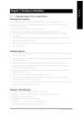
Страница 9 из 81 1-1 English Chapter 1 Hardware Installation Considerations Prior to Installation Preparing Your Computer The motherboard contains numerous delicate electronic circuits and components which can become damaged as a result of electrostatic discharge (ESD). Thus, prior to installation, please follow
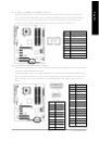
Страница 10 из 81 English 1-2 Feature Summary CPU Chipset Memory Slots IDE Connections FDD Connections Onboard SATA Peripherals Onboard LAN Onboard Audio I/O Control w w w w w w w w w w w w w w w w w w w w w w w w w w w w w w w Supports the latest Intel® Pentium® 4 LGA775 CPU Supports 800/533MHz FSB L2 cache varies
Страница 11 из 81 BIOS Additional Features Overclocking Form Factor w w w w w w w w w w w w w System voltage detection CPU temperature detection CPU / System / Power fan speed detection CPU warning temperature CPU / System / Power fan failure warning CPU smart fan control Use of licensed AWARD BIOS Supports Dual
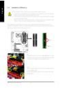
Страница 12 из 81 English 1-3 Installation of the CPU and Heatsink Before installing the CPU, please comply with the following conditions: 1. Please make sure that the motherboard supports the CPU. 2. Please take note of the one indented corner of the CPU. If you install the CPU in the wrong direction, the CPU will
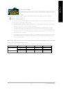
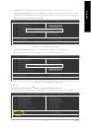
Страница 13 из 81 Male Push Pin The top of Female Push Pin Female Push Pin Fig.1 Please apply an even layer of heatsink paste on the surface of the installed CPU. Fig. 2 (Turning the push pin along the direction of arrow is to remove the heatsink, on the contrary, is to install.) Please note the direction of arrow
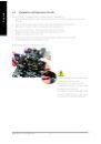
Страница 14 из 81 English 1-4 Installation of Memory Before installing the memory modules, please comply with the following conditions: 1. Please make sure that the memory used is supported by the motherboard. It is recommended that memory of similar capacity, specifications and brand be used. 2. Before installing
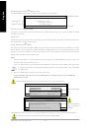
Страница 15 из 81 GA-8I915P-D Pro supports the Dual Channel Technology. After operating the Dual Channel Technology, the bandwidth of Memory Bus will add double up to 8.5GB/s. GA-8I915P-D Pro includes 4 DIMM sockets, and each Channel has two DIMM sockets as following: Channel A : DDR II 1, DDR II 2 Channel B : DDR
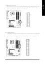
Страница 16 из 81 English 1-5 Installation of Expansion Cards You can install your expansion card by following the steps outlined below: 1. Read the related expansion card's instruction document before install the expansion card into the computer. 2. Remove your computer's chassis cover, screws and slot bracket from
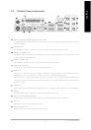
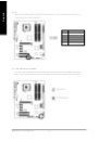
Страница 17 из 81 I/O Back Panel Introduction English 1-6 PS/2 Keyboard and PS/2 Mouse Connector To install a PS/2 port keyboard and mouse, plug the mouse to the upper port (green) and the keyboard to the lower port (purple). Parallel Port The parallel port allows connection of a printer, scanner and other
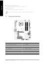
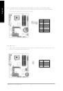
Страница 18 из 81 English Center/Subwoofer Speaker Out Connect the Center/Subwoofer speakers to this connector. Side Speaker Out Connect the side surround speakers to this connector. You can use audio software to configure 2-/4-/6-/8-channel audio functioning. 1-7 Connectors Introduction 3 1 5 2 8 13 12 6 4 7 9 18
Страница 19 из 81 ATX_12V/ATX (Power Connector) With the use of the power connector, the power supply can supply enough stable power to all the components on the motherboard. Before connecting the power connector, please make sure that all components and devices are properly installed. Align the power connector with
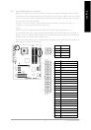
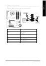
Страница 20 из 81 English 3/4/5) CPU_FAN / SYS_FAN / PWR_FAN (Cooler Fan Power Connector) The cooler fan power connector supplies a +12V power voltage via a 3-pin/4-pin (only for CPU_FAN) power connector and possesses a foolproof connection design. Most coolers are designed with color-coded power connector wires. A
Страница 21 из 81 The FDD connector is used to connect the FDD cable while the other end of the cable connects to the FDD drive. The types of FDD drives supported are: 360KB, 720KB, 1.2MB, 1.44MB and 2.88MB. Please connect the red power connector wire to the pin1 position. 34 33 2 1 8) IDE (IDE Connector) An IDE
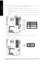
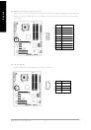
Страница 22 из 81 English 9) S_ATA0/S_ATA1/S_ATA2/S_ATA3 (Serial ATA Connector, Controlled by ICH6) Serial ATA can provide 150MB/s transfer rate. Please refer to the BIOS setting for the Serial ATA and install the proper driver in order to work properly. Pin No. 1 1 7 Definition GND 2 TXP 3 TXN 4 5 GND RXN 6 RXP 7
Страница 23 из 81 Please connect the power LED, PC peaker, reset switch and power switch etc of your chassis front panel to the F_PANEL connector according to the pin assignment below. Speaker Connector SPEAK- 20 19 Reset Switch SPEAK+ Power Switch Message LED/ Power/ Sleep LED HD (IDE Hard Disk Active LED) PW-
Страница 24 из 81 English 12) AZALIA_FP (Front Audio Connector) Please make sure the pin assigment on the cable is the same as the pin assigment on the motherboard header. To find out if the chassis you are buying support front audio panel connector, please contact your dealer. Pin No. Line2_R 6 FSENSE1 FAUOIO_JD No
Страница 25 из 81 Be careful with the polarity of the front USB connector. Check the pin assignment carefully while you connect the front USB cable, incorrect connection between the cable and connector will make the device unable to work or even damage it. For optional front USB cable, please contact your local
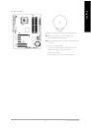
Страница 26 из 81 English 16) IR Be careful with the polarity of the IR connector while you connect the IR. Please contact your nearest dealer for optional IR device. Pin No. 1 Definition VCC 2 No Pin 3 IR RX 4 5 1 GND IR TX 17) CLR_CMOS (Clear CMOS) You may clear the CMOS data to its default values by this jumper.
Страница 27 из 81 English 18) BAT(Battery) Danger of explosion if battery is incorrectly replaced. Replace only with the same or equivalent type recommended by the manufacturer. Dispose of used batteries according to the manufacturer's instructions. If you want to erase CMOS... 1.Turn OFF the computer and unplug the
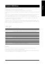
Страница 29 из 81 BIOS (Basic Input and Output Sy stem) includes a CMOS SETUP utility w hich allow s user to configure required settings or to activ ate certain sy stem features. The CMOS SETUP sav es the configuration in the CMOS SRAM of the motherboard. When the pow er is turned off, the battery on the motherboard
Страница 30 из 81 English The Main Menu (For example: BIOS Ver. : F3c) Once y ou enter Aw ard BIOS CMOS Setup Utility, the Main Menu (as figure below ) w ill appear on the screen. Use arrow key s to select among the items and press <Enter> to accept or enter the sub-menu. CMOS Setup Utility -Cop y right (C) 198
Страница 31 из 81 Optimized Defaults indicates the v alue of the sy stem parameters w hich the sy stem w ould be in best performance c onfiguration. n Set Supervisor Password Change, set, or disable passw ord. It allows y ou to limit access to the sy stem and Setup, or just to Setup. n Set User Password Change, set,
Страница 32 из 81 English 2-1 Standard CMOS Features CMOS Setup Utility -Cop y right (C) 198 4-2004 Award Software Stan dard CM OS Features Date(mm:dd:y y ) Time (hh:mm:ss) Thu, Ap r 29 2004 22:3 1:24 Item Help Menu Level} [None] [None] Change the day, month, y ear Drive A Driv e B Flopp y 3 Mode Suport [1.44M,
Страница 33 из 81 The category identifies the ty pes of floppy dis k driv e A or driv e B that has been installed in the computer. None No floppy driv e installed 360K, 5.25" 5.25 inch PC-ty pe standard drive; 360K by te capacity . 1.2M, 5.25" 5.25 inch AT-ty pe high-density driv e; 1.2M by te capacity (3.5 inch w
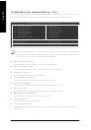
Страница 34 из 81 English 2-2 Advanced BIOS Features CMOS Setup Utility -Cop y right (C) 198 4-2004 Award Software Advanc ed BIOS Fe atures } Hard Disk Bo ot Prio rity First Boot De vice Second Bo ot Device Third Boo t Device Passwor d Check # CPUHy per-Threading Limit CPUID Max. to 3 higf: M ove F3: Language [Press
Страница 35 из 81 Enabled Disabled Enables CPU Hy per Threading Feature. Please note that this feature is only working for operating sy stem w ith multi processors mode supported. (Default v alue) Disables CPU Hy per Threading. Limit CPUID Max. to 3 Enabled Disabled Limit CPUID Max imum v alue to 3 w hen use older
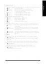
Страница 36 из 81 English 2-3 Integrated Peripherals CMOS Setup Utility -Cop y right (C) 198 4-2004 Award Software IntegratedPeripherals On-Chip Primary PCI IDE On-Chip SATA Mode x PATA IDE Se t to SATA Port 0/2 Se t to SATA Port 1/3 Se t to USB Contro ller USB 2 .0 Contr oller USB K ey board Su pport USB Mouse Supp
Страница 37 из 81 Disabled Auto Combined Disable this function. BIOS w ill auto detect. (Default v alue) Set On-Chip SATA mode to Combined, y ou can use up to 4 HDDs on the motherboard; 2 for SATA and the other for PATA IDE. Set On-Chip SATA mode to Enhanced, the motherboard allow s up to 6 HDDs to use. Set On-Chip
Страница 38 из 81 English Onboard LAN Boot ROM This function decide w hether to inv oke the boot ROM of the onboard LAN chip. Enabled Enable this function. Disabled Disable this function. (Default v alue) Onboard Serial P ort 1 Auto 3F8/IRQ4 2F8/IRQ3 3E8/IRQ4 2E8/IRQ3 Disabled BIOS w ill automatically setup the port
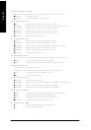
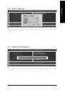
Страница 39 из 81 Power Management Setup English 2-4 CMOS Setup Utility -Cop y right (C) 198 4-2004 Award Software Power Manag ement Setup ACPI Susp end Ty pe Soft-Off b y PWR-BTTN PME E vent Wake Up Power On by Ring Resumeby Alarm x Date (of Month) Alarm x Time(hh:mm:ss) Alarm Power On By Mouse Power On By Key
Страница 40 из 81 English Power On By Keyboard Passw ord Disabled Key board 98 Enter from 1 to 5 characters to set the Key board Pow er On Passw ord. Disabled this function. (Default v alue) If y our key board hav e "POWER Key " button, y ou can press the key to pow er on the system. KB Power ON Password When "Pow
Страница 41 из 81 PnP/PCI Configurations CMOS Setup Utility -Cop y right (C) 198 4-2004 Award Software PnP/PCI Configur ations PCI 1 IRQ Assignment PCI 2 IRQ Assignment higf: M ove F3: Language Enter: Select F5: Previo us Values [Auto] [Auto] +/-/PU/P D:Value F10: Save F6: Fail-Safe De fault Item Help Menu Level}
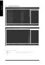
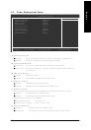
Страница 42 из 81 English 2-6 PC Health Status CMOS Setup Utility -Cop y right (C) 198 4-2004 Award Software PC H ealth Status Vcore DDR18V +3.3V +12V Current CPU Temperature Curren t CPU FAN Speed Curren t POWER FAN Speed Curr ent SYST EM FAN Speed CPU Warning Temperature CPU FAN Fail Wa rning POWER FAN Fail
Страница 43 из 81 In order to make "CPU Smart FAN Control" function w ork properly, please set the pin number according to the CPU FAN that you used. 3 PIN Set CPU FAN PIN Ty pe to 3 pin. (Default v alue) 4 PIN Set CPU FAN PIN Ty pe to 4 pin. 2-7 MB Intelligent Tweaker(M.I.T.) CMOS Setup Utility -Cop y right (C) 198
Страница 44 из 81 English CPU Host Clock Control Please note that if y our system is ov erclocked and cannot restart, please w ait 20secs. for automatic sy stem restart or clear the CMOS setup data and perform a safe restart. Disabled Disable CPU Host Clock Control. (Default v alue) Enabled Enable CPU Host Clock
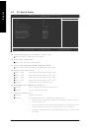
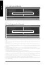
Страница 45 из 81 Select Language English 2-8 CMOS Setup Utility -Cop y right (C) 198 4-2004 Award Software } } } } } } } Stan dard CM OS Features Advanc ed BIOS Fe atures IntegratedPeripherals Power Manag ement Setup PnP/PCI Configur ations PC H ealth Status MB In telligent Tweaker(M. I.T.) Select L anguage Load
Страница 46 из 81 English 2-10 Load Optimized Defaults CMOS Setup Utility -Cop y right (C) 198 4-2004 Award Software } } } } } } } Stan dard CM OS Features Select L anguage Advanc ed BIOS Fe atures Load Fail-Safe Defaults IntegratedPeripherals Load Optimized Defaults Power Manag ement Setup Set Su pervisor Pa ssword
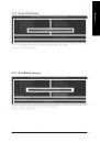
Страница 47 из 81 English 2-12 Save & Exit Setup CMOS Setup Utility -Cop y right (C) 198 4-2004 Award Software } } } } } } } Stan dard CM OS Features Select L anguage Advanc ed BIOS Fe atures Load Fail-Safe Defaults IntegratedPeripherals Load Optimized Defaults Power Manag ement Setup Set Su pervisor Pa ssword
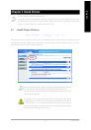
Страница 49 из 81 Pictures below are shown in Windows XP. Insert the driver CD-title that came with your motherboard into your CD-ROM drive, the driver CD-title will auto start and show the installation guide. If not, please double click the CD-ROM device icon in "My computer", and execute the Run.exe. 3-1 Install
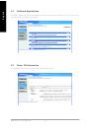
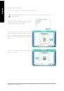
Страница 50 из 81 English 3-2 Software Applications This page displays all the tools that Gigabyte developed and some free software, you can choose anyone you want and press "install" to install them. 3-3 Driver CD Information This page lists the contents of software and drivers in this CD-title. GA-8I915P-D Pro
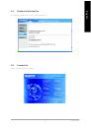
Страница 51 из 81 Hardware Information English 3-4 This page lists all device you have for this motherboard. 3-5 Contact Us Please see the last page for details. - 51 - Install Drivers
Страница 53 из 81 4-1 English Chapter 4 Appendix Unique Software Utilities (Not all model support these Unique Software Utilities, please check your MB features.) U-PLUS D.P.S. (Universal Plus Dual Power System) The U-Plus Dual Power System (U-Plus DPS) is a revolutionary eight-phase power circuit built for ultimate
Страница 54 из 81 English 4-1-1 Xpress Recovery Introduction What is Xpress Recovery ? Xpress Recovery is a utility used to back up and restore an OS partition. If the hard drive is not working properly, the user can restore the drive to its original state. 1. 2. 3. 4. 5. 6. Supports FAT16, FAT32, and NTFS formats
Страница 55 из 81 Press F9 during powering on the computer. (Text Mode) Press F9 during powering on the computer . English 2. Award Modular BIOS v6.00PG, An Energy Star Al ly Copyright (C) 1984-2004, Award Software, Inc. Intel 865PE AGPSet BIOS for 8IPE1000MT F1 Check System Health OK . . . F9 For Xpress Recovery
Страница 56 из 81 English 1. Execute Backup Utility: ! Press B to Backup your System or Esc to Exit The backup utility will automatically scan your system and back up data as a backup image in your hard drive. Not all systems support access to Xpress Recovery by pressing the F9 key during computer power on. If this
Страница 57 из 81 A. What is Dual BIOS Technology? Dual BIOS means that there are two system BIOS (ROM) on the motherboard, one is the Main BIOS and the other is Backup BIOS. Under the normal circumstances, the system works on the Main BIOS. If the Main BIOS is corrupted or damaged, the Backup BIOS can take over
Страница 58 из 81 English c. Dual BIOS Item explanation: Wide Range Protection: Disable(Default), Enable Status 1: If any failure (ex. Update ESCD failure, checksum error or reset? occurs in the Main BIOS, just before the Operating System is loaded and after the power is on, and that the Wide Range Protection is set
Страница 59 из 81 Please note that because updating BIOS has potential risk, please do it with caution!! We are sorry that Gigabyte Technology Co., Ltd is not responsible for damages of system because of incorrect manipulation of updating BIOS to avoid any claims from end-users. Before You Begin: Before you start
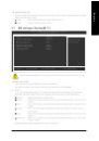
Страница 60 из 81 English Entering the Q-FlashTM utility: Step1: To use Q-Flash utility, you must press Del in the boot screen to enter BIOS menu. CMOS Setup Utility-Copyright (C) 1984-2004 Award Software } } Standard CMOS Features Advanced BIOS Features Select Language Load Fail-Safe Defaults } } Integrated
Страница 61 из 81 Steps: 1. Press arrow buttons on your keyboard to move the light bar to "Load Main BIOS from Floppy" item in the Q-Flash menu and press Enter button. Later, you will see a box pop up showing the BIOS files you previously downloaded to the floppy disk. If you want to save the current BIOS for backup
Страница 62 из 81 English 3. Press Y button on your keyboard after you are sure to update BIOS. Then it will begin to update BIOS. The progress of updating BIOS will be displayed. Please do not take out the floppy disk when it begins flashing BIOS. 4. Press any keys to return to the Q-Flash menu when the BIOS
Страница 63 из 81 Press Del to enter BIOS menu after system reboots. When you are in BIOS menu, move to Load Fail-Safe Defaults item and press Enter to load BIOS Fail-Safe Defaults. Normally the system redetects all devices after BIOS has been upgraded. Therefore, we highly recommend reloading the BIOS defaults
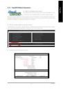
Страница 64 из 81 English Exploring the Q-FlashTM utility screen The Q-FlashBIOS utility screen consists of the following key components. Q-FlashTM utility bar Q-Flash Utility V1.30 Flash Type/Size.................................SST 49LF003A Task menu for Q-FlashTM utility Enter : Run Keep DMI Data Enable Update
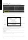
Страница 65 из 81 Press Y button on your keyboard after you are sure to update BIOS. Then it will begin to update BIOS. The progress of updating BIOS will be shown at the same time. Q-Flash Utility V1.30 Flash Type/Size.................................SST 49LF003A 256K Keep DMI Data BIOS Now Updating Enable Update
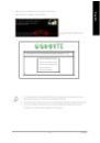
Страница 66 из 81 English Method 2 : @BIOSTM Utility If you do not have a DOS startup disk, we recommend that you use the new @BIOS utility. @BIOS allows users to update their BIOS under Windows. Just select the desired @BIOS server to download the latest version of BIOS. Fig 1. Installing the @BIOS utility Fig 2.
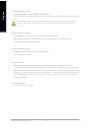
Страница 67 из 81 IV. Check out supported motherboard and Flash ROM: In the very beginning, there is "About this program" icon shown in dialog box. It can help you check out which kind of motherboard and which brand of Flash ROM are supported. 2. Note: I. In method I, if it shows two or more motherboard's model
Страница 68 из 81 English 4-1-3 2- / 4- / 6- / 8- Channel Audio Function Introduction This motherboard provide 6 audio connector. You are able to use 2-/ 4-/6-/8-channnels audio feature by audio software selection. Introduction of audio connectors: You may connect CD-ROM/DVD-ROM, walkman or others audio input to
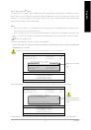
Страница 69 из 81 English STEP 3: Click "Speaker Configuration" then click on the left selection bar and select "2CH Speaker" to complete 2 channel audio configuration. 4 Channel Audio Setup STEP 1 : Connect the front channels to "Front Speaker Out", the rear channels to "Rear Speaker Out". Front Speaker Out Rear
Страница 70 из 81 English 6 Channel Audio Setup STEP 1 : Connect the front channels to "Front Speaker Out", the rear channels to "Rear Speaker Out", and the Center/Subwoofer channels to "Center/Subwoofer Speaker Out". Front Speaker Out Rear Speaker Out Center/Subwoofer Speaker Out STEP 2 : Following installation of
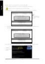
Страница 71 из 81 STEP 1 : Connect the front channels to "Front Speaker Out", the rear channels to "Rear Speaker Out", the Center/ Subwoofer channels to "Center/Subwoofer Speaker Out", and the side channels to "Side Speaker Out". Front Speaker Out Rear Speaker Out Center/Subwoofer Speaker Out Side Speaker Out STEP 2
Страница 72 из 81 English Jack-Sensing Introduction Jack-Sensing provides audio connectors error-detection function. Install Microsoft DirectX8.1 or later version before to enable Jack-Sensing support for Windows 2000. After you install an audio device, a screen of a list would pop up from the audio software for you
Страница 73 из 81 Troubleshooting Below is a collection of general asked questions. To check general asked questions based on a specific motherboard model, please log on to http://tw.giga-byte.com/faq/faq.htm Question 1: I cannot see some options that were included in previous BIOS after updating BIOS. Why? Answer:
Страница 74 из 81 English Question 7: Why cannot I use the IDE 2? Answer: Please refer to the user manual and check whether you have connected any cable that is not provided with the motherboard package to the USB Over Current pin in the Front USB Panel. If the cable is your own cable, please remove it from this pin