8
GB
use. If this is not the case, follow the instructions indicated
in the paragraph “Adapting to different types of gas.”
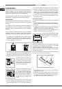
When using liquid gas from a cylinder, install a pressure
regulator which complies with current national regulations.
!
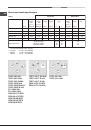
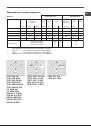
Check that the pressure of the gas supply is consistent with the
values indicated in Table 1 (“Burner and nozzle specifications”).
This will ensure the safe operation and longevity of your
appliance while maintaining efficient energy consumption.
Connection with a rigid pipe (copper or steel)
!
Connection to the gas system must be carried out in such a
way as not to place any strain of any kind on the appliance.
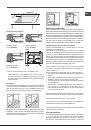
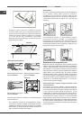
There is an adjustable L-shaped pipe fitting on the appliance
supply ramp and this is fitted with a seal in order to prevent
leaks. The seal must always be replaced after rotating the
pipe fitting (seal provided with appliance). The gas supply
pipe fitting is a threaded 1/2 gas cylindrical male attachment.
Connecting a flexible jointless stainless steel pipe to a
threaded attachment
The gas supply pipe fitting is a threaded 1/2 gas cylindrical
male attachment.
These pipes must be installed so that they are never longer
than 2000 mm when fully extended. Once connection has
been carried out, make sure that the flexible metal pipe
does not touch any moving parts and is not compressed.
!
Only use pipes and seals that comply with current national
regulations.
Checking the tightness of the connection
!
When the installation process is complete, check the pipe
fittings for leaks using a soapy solution. Never use a flame.
Adapting to different types of gas
To adapt the hob to a different type of gas other than default
type (indicated on the rating plate at the base of the hob or
on the packaging), the burner nozzles should be replaced
as follows:
1. Remove the hob grids and slide the burners off their
seats.
2. Unscrew the nozzles using a 7 mm socket spanner, and
replace them with nozzles for the new type of gas (see
table 1 “Burner and nozzle characteristics”).
3. Reassemble the parts following the above procedure in
the reverse order.
4. Once this procedure is finished, replace the old rating
sticker with one indicating the new type of gas used.
Sticker are available from any of our Service Centres.
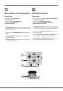
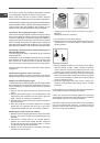
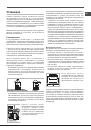
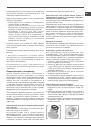
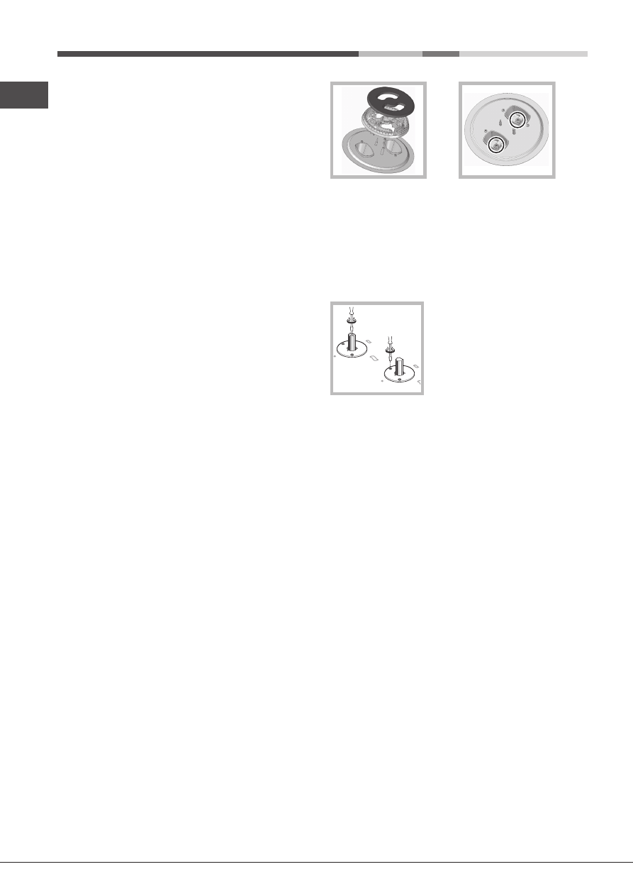
Replacing the Triple ring burner nozzles
1. Remove the pan supports and lift the burners out of their
housing. The burner consists of two separate parts (see
pictures).
2. Unscrew the nozzles using a 7 mm socket spanner.
Replace the nozzles with models that are configured
for use with the new type of gas (see Table 1). The two
nozzles have the same hole diameter.
3. Replace all the components by completing the above
operations in reverse order.
• Adjusting the burners’ primary air Does not require
adjusting.
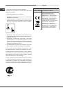
• Setting the burners to minimum
1. Turn the tap to the low flame position;
2. Remove the knob and adjust the adjustment screw, which
is positioned in or next to the tap pin, until the flame is
small but steady.
3. Having adjusted the flame to the required low setting,
while the burner is alight, quickly change the position
of the knob from minimum to maximum and vice versa
several times, checking that the flame does not go out.
4. Some appliances have a safety device (thermocouple)
fitted. If the device fails to work when the burners are set
to the low flame setting, increase this low flame setting
using the adjusting screw.
5. Once the adjustment has been made, replace the
seals on the by-passes using sealing wax or a similar
substance.
!
If the appliance is connected to liquid gas, the regulation
screw must be fastened as tightly as possible.
!
Once this procedure is finished, replace the old rating
sticker with one indicating the new type of gas used. Stickers
are available from any of our Service Centres.
!
Should the gas pressure used be different (or vary slightly)
from the recommended pressure, a suitable pressure
regulator must be fitted to the inlet pipe (in order to comply
with current national regulations).