13
GB
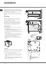
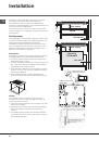
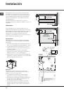
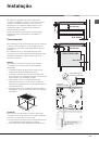
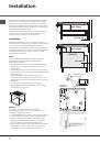
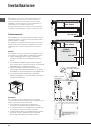
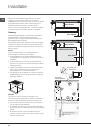
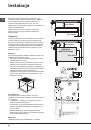
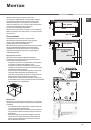
Fixing
The appliance must be installed
on a perfectly level
supporting surface. Any deformities caused by
improper fixing could affect the features and operation
of the hob.
The thickness of the supporting surface
should be taken
into account when choosing
the length of the screws for
the fixing hooks:
• 30 mm thick: 23 mm screws
• 40 mm thick: 13 mm screws
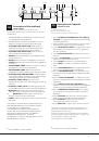
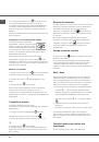
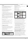
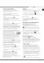
Fix the hob as follows:
1. Use short flat-bottomed screws to fix the 4 alignment
springs in the holes provided at the central point of each
side of the hob.
2. Place the hob in the cavity, make sure it is in a central
position and push down on the whole perimeter until the
hob is stuck to the supporting surface.
3. For hobs with raised sides: After inserting the hob into
its cavity, insert the 4 fixing hooks (each has its own pin)
into the lower edges of the hob, using the long pointed
screws to fix them in place, until the glass is stuck to the
supporting surface.
!
The screws for the alignment springs must remain
accessible.
!
In order to adhere to safety standards, the appliance
must not come into contact with electrical parts once it
has been installed.
!
All parts which ensure the safe operation of the
appliance must not be removable without the aid of a
tool.
Electrical connection
!
The electrical connection for the hob and for any built-
in oven must be carried out separately, both for safety
purposes and to make extracting the oven easier.
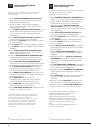
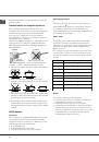
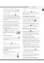
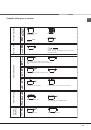
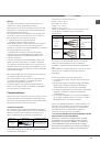
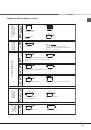
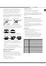
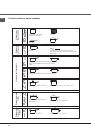
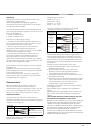
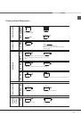
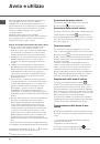
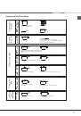
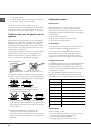
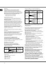
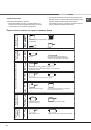
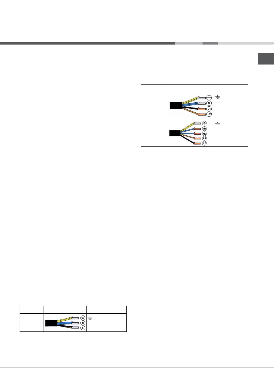
Single-phase connection
The hob is equipped with a pre-connected electricity
supply cable, which is designed for single-phase
connection. Connect the wires in accordance with the
instructions given in the following table and diagrams:
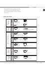
Voltage and
mains frequency
Electrical cable
Wire connection
220-240V 1+N ~
50 Hz
: yellow/green
N
: the two blue wires together
L
: brown and black together
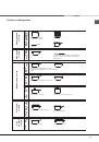
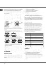
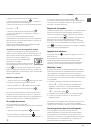
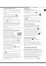
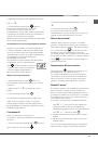
Other types of connection
If the mains supply corresponds with one of the
following:
Voltage and mains frequency
• 400V - 2+N ~ 50 Hz
• 220-240V 3 ~ 50 Hz
• 400V 3 - N ~ 50 Hz
• 400V - 2+2N ~ 50 Hz
Separate the wires and connect them in accordance with
the instructions given in the following table and diagrams:
Voltage and
mains frequency
Electrical cable
Wire connection
400V - 2+N ~
50 Hz
220-240V 3 ~
50 Hz
400V 3-N ~
50 Hz
: yellow/green;
N
: the two blue wires
together
L1
: black
L2
: brown
400V - 2+2N ~
50 Hz
: yellow/green;
N1
: blue
N2
: blue
L1
: black
L2
: brown
Connecting the electricity supply cable to the mains
If the appliance is being connected directly to the electricity
mains an omnipolar switch must be installed with a minimum
opening of 3 mm between contacts.
!
The installer must ensure that the correct electrical
connection has been made and that it is fully compliant
with safety regulations.
Before connecting the appliance to the power supply, make
sure that:
• The appliance is earthed and the plug is compliant with the
law.
• The socket can withstand the maximum power of the
appliance, which is indicated on the data plate located on
the appliance itself.
• The voltage falls within the range of values indicated on the
data plate.
• The socket is compatible with the plug of the appliance. If
the socket is incompatible with the plug, ask an authorised
technician to replace it. Do not use extension cords or
multiple sockets.
!
Once the appliance has been installed, the power supply
cable and the electrical socket must be easily accessible.
!
The cable must not be bent or compressed.
!
The cable must be checked regularly and replaced by
authorised technicians only.
!
The manufacturer declines any liability should these
safety measures not be observed.
!
Do not remove or replace the power supply cable for any
reason. Its removal or replacement will void the warranty
and the CE marking. INDESIT does not assume liability for
accidents or damage arising from replacement/removal
of the original power supply cable. Replacement can only
be accepted when carried out by personnel authorised by
INDESIT and using an original spare part.