Инструкция для HOTPOINT-ARISTON PC 750 T

(скачивание инструкции бесплатно)
Формат файла: PDF
Доступность: Бесплатно как и все руководства на сайте. Без регистрации и SMS.
Дополнительно: Чтение инструкции онлайн
background image

30

GB

when the appliance is not in use.

•  When unplugging the appliance always pull the plug from 

the mains socket, do not pull on the cable.

•  Never  carry  out  any  cleaning  or  maintenance  work 

without having detached the plug from the mains.

•  In case of malfunction, under no circumstances should 

you attempt to repair the appliance yourself. Repairs 

carried out by inexperienced persons may cause injury 

or further malfunctioning of the appliance. Contact a 

Service Centre (see Assistance).

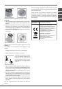
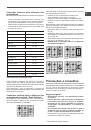
•  Always make sure that pan handles are turned towards 

the centre of the hob in order to avoid accidental burns.

•  Do not close the glass cover (if present) when the gas 

burners or electric hotplates are still hot.

•  Do not leave the electric hotplate switched on without a 

pan placed on it.

•  Do not use unstable or deformed pans.

•  The  appliance  should  not  be  operated  by  people 

(including children) with reduced physical, sensory or 

mental capacities, by inexperienced individuals or by 

anyone who is not familiar with the product. These 

individuals should, at the very least, be supervised by 

someone who assumes responsibility for their safety or 

receive preliminary instructions relating to the operation 

of the appliance.

•  Do not let children play with the appliance.

•  The  appliance  is  not  intended  to  be  operated  by 

means  of  an  external  timer  or  separate  remote-

control system.

Disposal

•  When  disposing  of  packaging  material:  observe  local 

legislation so that the packaging may be reused.

•  The  European  Directive  2012/19/EC  on  Waste 

Electrical and Electronic Equipment (WEEE), requires 

that old household electrical appliances must not 

be disposed of in the normal unsorted municipal 

waste stream. Old appliances must be collected 

separately in order to optimise the recovery and 

recycling of the materials they contain and reduce 

the impact on human health and the environment.  

The crossed out “wheeled bin” symbol on the product 

reminds you of your obligation, that when you dispose 

of the appliance it must be separately collected. 

  Consumers should contact their local authority or retailer 

for information concerning the correct disposal of their 

old appliance.

Maintenance and care

Switching the appliance off

Disconnect your appliance from the electricity supply before 

carrying out any work on it.

Cleaning the appliance

!

 Do not use abrasive or corrosive detergents such as stain 

removers, anti-rust products, powder detergents or sponges with 

abrasive surfaces: these may scratch the surface beyond repair.

!

 Never use steam cleaners or pressure cleaners on the 

appliance.

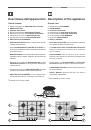
•   It is usually enough to wash the hob with a damp sponge 

and dry it with absorbent kitchen roll.

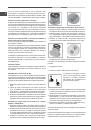
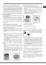
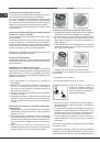
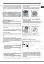
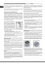
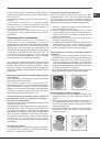
•  The removable parts of the burners should be washed 

frequently with warm water and soap and any burnt-on 

substances removed.

•  For hobs which ligth automatically, the terminal part of 

the electronic instant lighting devices should be cleaned 

frequently and the gas outlet holes should be checked 

for blockages.

•  The electric hotplates should be cleaned with a damp 

cloth and lubricated with a little oil while still warm.

•  Stainless steel can be marked by hard water that has 

been left on the surface for a long time, or by aggressive 

detergents containing phosphorus. After cleaning, rinse 

and dry any remaining drops of water.

Gas tap maintenance

Over time, the taps may become jammed or difficult to turn. 

If this happens, the tap must be replaced.

!


This  procedure  must  be  performed  by  a  qualified 

technician authorised by the manufacturer.

Troubleshooting

It may happen that the appliance does not function properly 

or at all. Before calling the service centre for assistance, 

check if anything can be done. First, check to see that there 

are no interruptions in the gas and electrical supplies, and, 

in particular, that the gas valves for the mains are open.

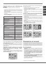
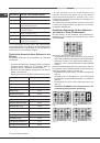
The  burner  does  not  light  or  the  flame  is  not  even 

around the burner.

Check whether:

•  The gas holes on the burner are clogged.

•  All  the  movable  parts  that  make  up  the  burner  are 

mounted correctly.

•  There are draughts near the appliance.

The flame dies in models with a safety device.

Check to make sure that:

•  You pressed the knob all the way in.

•  You keep the knob pressed in long enough to activate 

the safety device.

•  The gas holes are not blocked in the area corresponding 

to the safety device.

1
2
3
4
5
6
7
8
9
10
11
12
13
14
15
16
17
18
19
20
21
22
23
24
25
26
27
28
29
30
31
32
33
34
35
36
37
38
39
40
41
42
43
44
45
46
47
48
49
50
51
52
53
54
55
56
57
58
59
60
61
62
63
64
65
66
67
68
69
70
71
72
73
74
75
76
77
78
79
80
81
82
83
84
85
86
87
88
Оглавление инструкции
  • Страница 1 из 89
    PC 750 T GH /HA PC 750 T R /HA PC 760 F X /HA Français Mode d’emploi TABLE DE CUISSON Sommaire Mode d’emploi,1 Avertissements,4 Assistance,8 Description de l’appareil,11 Installation,32 Mise en marche et utilisation,38 Précautions et conseils,39 Nettoyage et entretien,40 Anomalies et remèdes,41
  • Страница 2 из 89
    Deutsch Bedienungsanleitung KOCHMULDE Inhaltsverzeichnis Bedienungsanleitung,2 Hinweise,5 Kundendienst,9 Beschreibung Ihres Gerätes,12 Installation,60 Inbetriebsetzung und Gebrauch,65 Vorsichtsmaßregeln und Hinweise,67 Reinigung und Pflege,67 Störungen und Abhilfe,68 Nederlands Gebruiksaanwijzing
  • Страница 3 из 89
    Avvertenze ATTENZIONE: Questo apparecchio e le sue parti accessibili diventano molto caldi durante l’uso. Bisogna fare attenzione ed evitare di toccare gli elementi riscaldanti. Tenere lontani i bambini inferiori agli 8 anni se non continuamente sorvegliati. Il presente apparecchio può essere
  • Страница 4 из 89
    The appliance is not intended to be operated by means of an external timer or separate remote control system. CAUTION: the use of inappropriate hob guards can cause accidents. Avertissements ATTENTION : Cet appareil ainsi que ses parties accessibles deviennent très chauds pendant leur
  • Страница 5 из 89
    la llama, por ejemplo, con una tapa o con ATENÇÃO: Deixar um fogão com una manta ignífuga. gordura e óleo sem vigilância pode ser perigoso e provocar um incêndio. ATENCIÓN: Riesgo de incendio: no deje NUNCA tente apagar as chamas com objetos sobre las superficies de cocción. água. É necessário
  • Страница 6 из 89
    sie wurden in den sicheren Gebrauch des Geräts eingewiesen und haben eine ausreichende Wahrnehmung der mit dem Gebrauch des Geräts verbundenen Gefahren. Erlauben Sie Kindern nicht, mit dem Gerät zu spielen. Reinigungsund Wartungsarbeiten dürfen nicht von unbewachten Kindern ausgeführt werden. ZUR
  • Страница 7 из 89
    Het apparaat is niet geschikt om te worden ingeschakeld m.b.v. een externe timer of door een gescheiden afstandsbedieningssysteem. Никогда не используйте паровые чистящие агрегаты или агрегаты под высоким давлением для чистки изделия. PAS OP: het gebruik van ongeschikte kookplaatbeschermingen kan
  • Страница 8 из 89
    Assistenza Comunicare: • il tipo di anomalia • il modello della macchina (Mod.) • il numero di serie (S/N) Queste ultime informazioni si trovano sulla targhetta caratteristiche posta sull’apparecchio. Non ricorrete mai a tecnici non autorizzati e rifiutate sempre l’installazione di pezzi di
  • Страница 9 из 89
    Assistência Comunique: • o modelo da máquina (Mod.) • o número de série (S/N) Estas últimas informações encontram-se na placa de identificação situada no aparelho e/ou na embalagem. ! Nunca recorra a técnicos não autorizados e sempre recuse a instalação de peças de reposição não originais.
  • Страница 10 из 89
    Descrizione dell’apparecchio Description of the appliance Vista d’insieme Overall view 1 2 3 4 5 6 7 8 1 2 3 4 5 6 7 8 Griglie di appoggio per RECIPIENTI DI COTTURA BRUCIATORI GAS PIASTRA ELETTRICA* Spia di funzionamento PIASTRA ELETTRICA* Manopole di comando della PIASTRA ELETTRICA* Manopole di
  • Страница 11 из 89
    Description de l’appareil Descripción del aparato Vue d’ensemble Vista en conjunto 1 2 3 4 5 6 7 8 1 2 3 4 Grilles support de CASSEROLES BRÛLEURS À GAZ PLAQUE ÉLECTRIQUE* Voyant fonctionnement des PLAQUE ÉLECTRIQUE* Manettes de commande des PLAQUE ÉLECTRIQUE* Manettes de commande des BRÛLEURS GAZ
  • Страница 12 из 89
    Descrição do aparelho Beschreibung Ihres Gerätes Vista de conjunto Geräteansicht 1 2 3 4 5 6 7 8 1 2 3 4 5 6 7 8 Grades de suporte para RECIPIENTES DE COZEDURA QUEIMADORES DE GÁS CHAPA ELÉCTRICA* Indicador luminoso CHAPA ELÉCTRICA* Selectores de comando das CHAPA ELÉCTRICA* Manípulos de comando dos
  • Страница 13 из 89
    Beschrijving van het apparaat Описание изделия Algemeen aanzicht Общии вид 1 2 3 4 5 1 2 3 4 Roosters voor PANNEN GASBRANDERS ELEKTRISCHE KOOKPLAAT* Controlelampje WERKING ELEKTRISCHE KOOKPLAAT* Knoppen voor het regelen van de ELEKTRISCHE KOOKPLAAT* 6 Knoppen voor het regelen van de GASBRANDERS 7
  • Страница 14 из 89
    Posizionamento ! Gli imballaggi non sono giocattoli per bambini e vanno eliminati secondo le norme per la raccolta differenziata (vedi Precauzioni e consigli). ! L’installazione va effettuata secondo queste istruzioni e da personale professionalmente qualificato. Una errata installazione può
  • Страница 15 из 89
    Collegamento elettrico Schema di fissaggio dei ganci Posizione gancio per top H=20mm Posizione gancio per top H=30mm Avanti Posizione gancio per top H=40mm Allacciamento del cavo di alimentazione alla rete Montare sul cavo una spina normalizzata per il carico indicato nella targhetta
  • Страница 16 из 89
    IT ! Per un sicuro funzionamento, per un adeguato uso dell’energia e maggiore durata dell’apparecchiatura, assicurarsi che la pressione di alimentazione rispetti i valori indicati nella tabella 1 “Caratteristiche dei bruciatori ed ugelli”. Allaccio con tubo rigido (rame o acciaio) ! L’allaccio
  • Страница 17 из 89
    ! Qualora la pressione del gas utilizzato sia diversa (o variabile) da quella prevista, è necessario installare, sulla tubazione d’ingresso un appropriato regolatore di pressione (secondo EN 88-1 e EN 88-2). IT TARGHETTA CARATTERISTICHE Collegamenti vedi targhetta caratteristiche elettrici Questa
  • Страница 18 из 89
    IT Caratteristiche dei bruciatori ed ugelli Tabella 1 Gas liquido Bruciatore Diametro (mm) Potenza termica kW (p.c.s.*) Ridotta (mm) *** ** Potenza termica kW (p.c.s.*) Nominale Rapido (R) 100 0.70 3.00 39 86 218 214 3.00 132 (H) 286 Rapido Ridotto (RR) 100 0.70 2.60 39 80 189 186 2.60 122 (H) 248
  • Страница 19 из 89
    Avvio e utilizzo ! Su ciascuna manopola è indicata la posizione del bruciatore gas o della piastra elettrica* corrispondente. Bruciatori gas Il bruciatore prescelto può essere regolato dalla manopola corrispondente come segue: ● Il bruciatore è dotato di accensione elettronica che entra in funzione
  • Страница 20 из 89
    IT Consigli pratici per l’uso dei bruciatori Al fine di ottenere il massimo rendimento è utile ricordare quanto segue: • utilizzare recipienti adeguati a ciascun bruciatore (vedere tabella) al fine di evitare che le fiamme fuoriescano dal fondo dei recipienti. • utilizzare sempre recipienti a fondo
  • Страница 21 из 89
    • Non toccare la macchina a piedi nudi o con le mani o i piedi bagnati o umidi. • L’apparecchio deve essere usato per cuocere alimenti, solo da persone adulte e secondo le istruzioni riportate in questo libretto. Ogni altro uso (ad esempio: riscaldamento di ambienti) è da considerarsi improprio e
  • Страница 22 из 89
    IT La fiamma non rimane accesa nelle versioni con sicurezza. Avete controllato se: • Non avete premuto a fondo la manopola. • Non avete mantenuto premuta a fondo la manopola per un tempo sufficiente ad attivare il dispositivo di sicurezza. • Sono ostruiti i fori di fuoriuscita del gas in
  • Страница 23 из 89
    ! Keep packaging material out of the reach of children. It can become a choking or suffocation hazard (see Precautions and tips). ! The appliance must be installed by a qualified professional according to the instructions provided. Incorrect installation may cause harm to people and animals or may
  • Страница 24 из 89
    GB Electrical connection Hook fastening diagram Hooking position for top H=20mm Hooking position for top H=30mm Front Hooking position for top H=40mm Back ! Use the hooks contained in the “accessory pack”. • Where the hob is not installed over a built-in oven, a wooden panel must be installed as
  • Страница 25 из 89
    Connection with a rigid pipe (copper or steel) ! Connection to the gas system must be carried out in such a way as not to place any strain of any kind on the appliance. There is an adjustable L-shaped pipe fitting on the appliance supply ramp and this is fitted with a seal in order to prevent
  • Страница 26 из 89
    GB DATA PLATE Electrical see data plate connections This appliance conforms to the following European Economic Community directives: - 2006/95/EEC dated 12/12/06 (Low Voltage) and subsequent amendments - 2004/108/EEC dated 15/12/04 (Electromagnetic Compatibility) and subsequent amendments -
  • Страница 27 из 89
    Burner and nozzle specifications Table 1 Liquid Gas Burner Diameter Thermal power kW (p.c.s.*) Nominal By-pass 1/100 (mm) Thermal power kW (p.c.s.*) Reduced (mm) (mm) Fast (R) 100 0.70 3.00 39 Reduced Fast (RR) 100 0.70 2.60 Semi Fast (S) 75 0.40 Auxiliary (A) 55 Triple Crown (TC) Ultrarapid (UR)
  • Страница 28 из 89
    GB Start-up and use ! The position of the corresponding gas burner or electric hotplate* is shown on every knob. Gas burners Each burner can be adjusted to one of the following settings using the corresponding control knob: ● Off Minimum To light one of the burners, hold a lit match or lighter near
  • Страница 29 из 89
    Burner Ø Cookware Diameter (cm) Rapid (R) 24 - 26 Reduced Rapid (RR) 24 - 26 Semi-Rapid (S) 16 - 20 Auxiliary (A) 10 - 14 Triple Crown (TC) 24 - 26 • Single burner for medium size cookware (diameter of 16-20 cm) (Fig. C). • NEVER use the double burner in the configuration represented in figure D.
  • Страница 30 из 89
    GB when the appliance is not in use. • When unplugging the appliance always pull the plug from the mains socket, do not pull on the cable. • Never carry out any cleaning or maintenance work without having detached the plug from the mains. • In case of malfunction, under no circumstances should you
  • Страница 31 из 89
    The burner does not remain lit when set to minimum. GB Check to make sure that: • The gas holes are not blocked. • There are no draughts near the appliance. • The minimum setting has been adjusted properly. The cookware is unstable. Check to make sure that: • The bottom of the cookware is perfectly
  • Страница 32 из 89
    FR BE LU NL Installation ! Conservez ce mode d’emploi pour pouvoir le consulter à tout moment. En cas de vente, de cession ou de déménagement, veillez à ce qu’il suive l’appareil pour informer le nouveau propriétaire sur son fonctionnement et lui fournir les conseils correspondants. ! Lisez
  • Страница 33 из 89
    600mm min. 420mm min. 650mm min. • Les éléments hauts jouxtant la hotte doivent être placés à au moins 420 mm de distance du plan de travail (voir figure). En cas d’installation de la table de cuisson sous un élément haut, ce dernier devra être monté à au moins 700 mm de distance du plan. Aération
  • Страница 34 из 89
    FR BE LU NL • la prise est bien compatible avec la fiche de l’appareil. Si ce n’est pas le cas, remplacez la prise ou la fiche, n’utilisez ni rallonges ni prises multiples. ! Après installation de l’appareil, le câble électrique et la prise de courant doivent être facilement accessibles ! Le câble
  • Страница 35 из 89
    ! En fin d’opération remplacez la vieille étiquette par celle correspondant au nouveau gaz utilisé, disponible dans nos Services Après-vente. Remplacement des injecteurs du brûleur Triple couronne 1. retirer les grilles et sortir les brûleurs de leurs logements. Le brûleur est formé de deux parties
  • Страница 36 из 89
    FR Caractéristiques des brûleurs et des injecteurs Tableau 1 (Pour la France et la Belgique) BE Brûleur LU NL Gaz liquidés Diamêtre Puissance Puissance By-pass Injecteur thermique thermique 1/100 1/100 kW kW (p.c.s.*) (p.c.s.*) Gaz natural Débit * (g/h) Injecteur Puissance 1/100 thermique kW
  • Страница 37 из 89
    FR Cat. I2E Pour la Luxembourg Gaz natural Brûleur Diamêtre (mm) Puissance thermique kW (p.c.s.*) Nominale Réduit Injecteur 1/100 (mm) Débit * (l/h) 100 3.00 0.70 132 (H) 286 Rapide Réduit (RR) 100 2.60 0.70 122 (H) 248 Semi Rapide (S) 75 1.65 0.40 96 (Z) 157 Auxiliaire (A) 55 1.00 0.40 79 (6) 95
  • Страница 38 из 89
    FR Mise en marche et utilisation BE ! La position du brûleur gaz ou de la plaque électrique* correspondante est indiquée sur chaque manette. LU NL Brûleurs à gaz Chaque manette permet de régler le brûleur sélectionné comme suit : ● ● Eteint Eteint Maximum Maximum Minimum Minimum Pour allumer un
  • Страница 39 из 89
    Conseils pratiques pour l’utilisation des brûleurs Pour obtenir un meilleur rendement, n’oubliez pas : • d’utiliser des récipients appropriés à chaque brûleur (voir tableau) pour éviter que les flammes ne dépassent de sous les casseroles. • de toujours utiliser des casseroles à fond plat et avec
  • Страница 40 из 89
    FR BE LU NL • Cet appareil ne doit pas être installé en extérieur, même dans un endroit abrité, il est en effet très dangereux de le laisser exposé à la pluie et aux orages. • Ne touchez pas à l’appareil si vous êtes pieds nus ou si vous avez les mains ou les pieds mouillés ou humides. • Cet
  • Страница 41 из 89
    Anomalies et remèdes FR Il peut arriver que l’appareil ne fonctionne pas ou ne fonctionne pas très bien. Avant d’appeler le service aprèsvente, voyons ensemble que faire. Vérifiez avant tout s’il n’y a pas de coupure de gaz ou de courant, et si les robinets du gaz en amont de l’appareil sont bien
  • Страница 42 из 89
    Instalación Colocación • Los gases de petróleo licuados, más pesados que el aire, se depositan en las partes más bajas. Por lo tanto, los ambientes que contienen botellas de GPL deben tener aberturas hacia el exterior para permitir la evacuación desde abajo de eventuales escapes de gas. Además, las
  • Страница 43 из 89
    Conexión eléctrica Esquema de fijación de los ganchos Posición del gancho para superficies H=20mm Posición del gancho para superficies H=30mm Adelante Posición del gancho para superficies H=40mm Conexión del cable de alimentación eléctrica a la red Instale en el cable un enchufe normalizado para la
  • Страница 44 из 89
    ES Conexión con tubo rígido (cobre o acero) ! La conexión a la red de gas se debe efectuar de modo que no provoque esfuerzos de ningún tipo al aparato. En el tubo de alimentación del aparato se encuentra una unión en “L” orientable, cuya estanqueidad está asegurada por una junta. Si resultara
  • Страница 45 из 89
    ES ! Cuando la presión del gas utilizado sea distinta de la prevista (o variable), es necesario instalar, en la tubería de entrada, un regulador de presión conforme con las Normas Nacionales en vigencia. PLACA DE CARACTERÍSTICAS Conexiones ver placa de características eléctricas Este aparato es
  • Страница 46 из 89
    ES Características de los quemadores e inyectores Tabla 1 Gas liquido Quemador Diametro Gas natural Potencia térmica kW (p.c.s.*) Nominal By-pass 1/100 Pico 1/100 Capacid.* (g/h) (mm) Potencia térmica kW (p.c.s.*) Reducida Pico 1/100 ** Potencia térmica kW (p.c.s.*) Nominal (mm) (mm) *** Ràpido (R)
  • Страница 47 из 89
    Puesta en funcionamiento y uso ! En cada mando está indicada la posición del quemador a gas o de la placa eléctrica* correspondiente. Quemadores a gas El quemador elegido se puede regular con el mando correspondiente de la siguiente manera: ● Apagado Para encender la corona deseada presionar a fond
  • Страница 48 из 89
    ES ! Antes de utilizarlas por primera vez, es necesario calentar las placas de cocción a la máxima temperatura durante 4 minutos, sin olla. Durante esta fase inicial, el revestimiento protector se endurece y alcanza la máxima resistencia. Consejos prácticos para el uso de los quemadores Si desea
  • Страница 49 из 89
    en la placa de características. • El aparato ha sido fabricado para un uso de tipo no profesional en el interior de una vivienda. • El aparato no se debe instalar al aire libre, tampoco si el espacio está protegido porque es muy peligroso dejarlo expuesto a la lluvia y a las tormentas. • No toque
  • Страница 50 из 89
    ES gas y eléctrica, y en particular, que las llaves de gas, aguas arriba del aparato, estén abiertas. El quemador no se enciende o la llama no es uniforme. Controle si: • Los orificios de salida de gas del quemador están obstruidos. • Se han colocado correctamente todas las partes móviles que
  • Страница 51 из 89
    Instalação Posicionamento • Os gases de liquefeitos de petróleo, mais pesados do que o ar, estagnam-se embaixo. Portanto, as salas que contiverem cilindros de GLP devem possuir aberturas para fora, de maneira que possibilitem o escoamento para baixo dos eventuais escapes de gás. Portanto os
  • Страница 52 из 89
    PT Ligação eléctrica Esquema para prender os ganchos Posição do gancho para H=20mm Posição do gancho para H=30mm Frente Posição do gancho para H=40mm Os planos equipados com cabo de alimentação de três pólos são predispostos para o funcionamento com uma corrente alternada na tensão e a frequência
  • Страница 53 из 89
    ! Para garantir um funcionamento seguro, uma utilização de energia apropriada e maior duração da aparelhagem, assegurar-se que a pressão de alimentação respeite os valores indicados na tabela 1 “Características dos queimadores e dos bicos”. Ligação com tubo rígido (cobre ou aço) ! A ligação do
  • Страница 54 из 89
    PT ! Ao terminar a operação substitua a velha etiqueta de calibragem com a que corresponde ao novo gás utilizado que se acha nos nossos Centros de Assistência Técnica. ! Se a pressão do gás utilizado for diferente (ou variável) daquela prevista, é necessário instalar na tubagem de entrada um
  • Страница 55 из 89
    Características dos queimadores e bicos PT Gás liquefeito Tabela 1 Queimador Diâmetro Potenza termica kW (p.c.s.*) Nomin. By-pass 1/100 (mm) Poténcia térmica kW (p.c.s.*) Reduz. *** ** Poténcia térmica kW (p.c.s.*) Nomin. Ràpido (R) 100 0.70 3.00 39 86 218 214 3.00 132 (H) 286 Ràpido Reduz. (RR)
  • Страница 56 из 89
    PT Início e utilização ! Em cada selector está indicada a posição do queimador de gás ou da chapa eléctrica* correspondente. Queimadores a gás O queimador escolhido pode ser regulado mediante o respectivo botão da seguinte maneira : ● Mínimo Para acender o queimador aproxime do mesmo a chama de um
  • Страница 57 из 89
    Conselhos práticos para utilização dos queimadores Para obter a máxima performance é bom lembrar-se do seguinte: • utilize recipientes adequados para cada um dos queimadores (veja a tabela) com o objectivo de evitar que as chamas ultrapassem o fundo dos recipientes. • utilize sempre recipientes de
  • Страница 58 из 89
    PT • Este aparelho não deve ser instalado ao ar livre, mesmo num sítio protegido, porque é muito perigoso deixá-lo exposto a chuva e temporais. • Não toque na máquina se estiver descalço, ou se as suas mãos ou pés estiverem molhados ou húmidos. • O aparelho deve ser utilizado para cozinhar
  • Страница 59 из 89
    Anomalias e soluções PT Pode acontecer do plano não funcionar ou não funcionar bem. Antes de chamar a assistência técnica, vejamos o que é possível fazer. Antes de mais nada, verifique que não haja interrupções nas redes de alimentação de gás e electricidade, especialmente se as torneiras do gás
  • Страница 60 из 89
    ! Bewahren Sie diese Bedienungsanleitung bitte sorgfältig auf, damit Sie sie jederzeit zu Rate ziehen können. Sorgen Sie dafür, dass sie im Falle eines Verkaufs, eines Umzugs oder einer Übergabe an einen anderen Benutzer das Gerät stets begleitet, damit auch der Nachbesitzer die Möglichkeit hat,
  • Страница 61 из 89
    sollten sämtliche zur Verfügung stehenden Haken verwendet werden. 555 mm m mm m 475 55 Zuluftöffnungen vorgesehen werden, um eine geeignete Belüftung im Innern des Umbauschrankes zu gewährleisten (siehe Abbildungen). Elektroanschluss Haken-Befestigungsschema Position der Haken für Arbeitsplatten
  • Страница 62 из 89
    BE ! Das Kabel muss regelmäßig kontrolliert werden und darf nur durch autorisiertes Fachpersonal ausgetauscht werden (siehe Kundendienst). ! Verwenden Sie ausschließlich Schläuche und Dichtringe, die den jeweilig gültigen inländischen Normen entsprechen. ! Der Hersteller lehnt jede Verantwortung
  • Страница 63 из 89
    TYPENSCHILD BE Elektrischer siehe Typenschild Anschluss • Einstellung der Brenner-Primärluft An den Brennern ist keine Primärlufteinstellung erforderlich. • Minimumeinstellung 1. Drehen Sie den Brenner auf Minimum; 2. Ziehen Sie den Reglerknopf ab und verstellen Sie dann die innen oder seitlich der
  • Страница 64 из 89
    BE Merkmale der Brenner und Düsen Tabelle 1 Erdgas Brenner Flüssigas Wärmeleistung kW (p.c.s.*) Menge* (l/h) G20 Nominal G25 3.00 286 3.00 332 2.60 248 2.60 288 96 (Z) 1.65 157 1.65 183 71 79 (6) 1.00 95 1.00 111 240 236 103x2 3.30 314 3.30 365 91 247 243 123 3.40 324 3.40 376 39 60 109 107 88 1.50
  • Страница 65 из 89
    Inbetriebsetzung und Gebrauch Zur Zündung eines jeden Flammenkranzes drücken Sie den entsprechenden Reglerknopf bis zum Anschlag und drehen ihn ! Auf jedem Reglerknopf ist gekennzeichnet, welcher Gasflamme oder Elektroplatte* er entspricht. dann gegen den Uhrzeigersinn bis auf maximale Einstellung
  • Страница 66 из 89
    BE Einstellung. Normal- oder Schnellkochplatte 0 Ausgeschaltet. 1 Garen von Gemüse, Fisch. 2 Kartoffeln (dämpfen) Gemüsesuppen, Kichererbsen, Bohnen. 3 Weitergaren von Eintopfgerichten und Gemüsesuppen. 4 Braten (mäßige Hitze). 5 Braten (starke Hitze). --------Anbraten von Fleisch und rasches
  • Страница 67 из 89
    Vorsichtsmaßregeln und Hinweise ! Das Gerät wurde entsprechend den strengsten internationalen Sicherheitsvorschriften entworfen und gebaut. Nachstehende Hinweise werden aus Sicherheitsgründen geliefert und sollten aufmerksam gelesen werden. Allgemeine Sicherheit • Dieses Gerät bezieht sich auf ein
  • Страница 68 из 89
    stehenbleiben. Es ist ratsam, diese Teile nach der Reinigung gut nachzuspülen und trockenzureiben. Übergekochtes Wasser muss ebenfalls beseitigt werden. BE Wartung der Gashähne Im Laufe der Zeit könnte der Gashahn blockieren oder sich nur schwer drehen lassen. In einem solchen Fall ist der Hahn
  • Страница 69 из 89
    Het installeren ! Bewaar dit boekje zorgvuldig voor eventuele verdere raadpleging. Wanneer u het product weggeeft, verkoopt, of wanneer u verhuist, dient u dit boekje bij het apparaat te bewaren zodat alle nodige informatie voorhanden blijft. ! Lees de gebruiksaanwijzingen zorgvuldig door: er staat
  • Страница 70 из 89
    De bevestigingsklemmen maken een bevestiging mogelijk van de kookplaat aan een keukenblad van tussen de 20 en 40 mm dik. Voor een goede bevestiging raden wij u aan alle bijgeleverde haken te gebruiken. NL BE 555 mm m mm m 475 55 Als de kookplaat wordt geïnstalleerd boven een inbouwoven die niet
  • Страница 71 из 89
    ! De kabel mag niet worden gebogen of samengedrukt. ! De kabel moet van tijd tot tijd worden gecontroleerd en mag alleen door erkende monteurs worden vervangen (zie Service). ! De fabrikant kan nergens aansprakelijk voor worden gesteld als deze normen niet worden nageleefd. Gasaansluiting De
  • Страница 72 из 89
    TYPEPLAATJE NL Elektrische zie typeplaatje aansluitingen BE • Regelen primaire lucht van de straalpijpjes (voor België) De branders hebben geen regeling van de primaire lucht nodig. • Het regelen van de minimumstand (voor België) 1. Zet het kraantje op de minimumstand; 2. Verwijder de knop en draai
  • Страница 73 из 89
    Kenmerken van de branders en de straalpijpjes Table 1 (Voor Belgie) Gaspit NL Vloeibaar gas Doorsnee Termisch Termisch vermogen vermogen kW kW (mm) (p.c.s.*) (p.c.s.*) By-pass Straal. 1/100 1/100 Gered. Nomin. (mm) Natuurlijk gas Bereik* (g/h) (mm) Butane Propane Straal. Termisch Bereik* Termisch
  • Страница 74 из 89
    NL A A R BE Ø145 R S S PC 640 T X/HA PC 640 T GH/HA PC 640 T AX/HA PC 640 T R/HA PC 640T GH R /HA PC 640 T E X/HA RR TC S RR UR A PC 730 RT GH /HA PC 730 RT X /HA TC S PC 640 X/HA PC 640 R/HA PC 640 /HA PC 631 X/HA PC 631 /HA 74 RR S S DC A PC 750 X /HA PC 750 AX /HA S RR S S A A TC S A PC 750 T X
  • Страница 75 из 89
    Starten en gebruik ! Op iedere knop staat aangegeven waar de gasbrander of de elektrische plaat* zich precies bevindt. Gasbranders De gekozen brander kan met de betreffende knop als volgt worden geregeld: ● ● Uit Maximum Minimum Uit Maximum Om de brander uit te doen moet u de knop geheel met de
  • Страница 76 из 89
    NL BE Praktisch advies voor het gebruik van de branders Voor een optimaal rendement dient u het volgende te onthouden: • gebruik voor iedere brander de pan die erop past (zie tabel) om te vermijden dat de vlammen er onderuit vandaan komen. • gebruik alleen pannen met een platte bodem en met een
  • Страница 77 из 89
    • Raak het apparaat niet blootsvoets aan of met natte handen of voeten. • Het apparaat dient gebruikt te worden om voedsel te bereiden. Het mag uitsluitend door volwassenen worden gebruikt en alleen volgens de instructies die in deze handleiding beschreven staan. Elk ander gebruik (bv.: verwarming
  • Страница 78 из 89
    NL BE De brander gaat niet aan of de vlam is niet gelijkmatig. Heeft u gecontroleerd of: • De openingen van de vlamverspreiders niet verstopt zijn. • Alle onderdelen van de brander goed in elkaar zitten. • Het niet tocht dichtbij het kookvlak. De vlam blijft niet aan in de uitvoeringen met
  • Страница 79 из 89
    ! Важно сохранить данное руководство для его последующих консультации. В случае продажи, передачи изделия или при переезде на новое место жительства необходимо проверить, чтобы руководство оставалось вместе с изделием, для того чтобы его новыи владелец мог ознакомиться с правилами эксплуатации и с
  • Страница 80 из 89
    555 mm RS m mm m 475 55 Если варочная панель устанавливается сверху встроенного духового шк афа, не оснащенного принудительнои охладительнои вентиляциеи, для надлежащеи вентиляции внутри кухонного элемента необходимо проделать вентиляционные отверстия для циркуляции воздуха (см чертежи). Схема
  • Страница 81 из 89
    ! Изделие должно быть установлено таким образом, чтобы электрическии провод и сетевая розетка были легко доступны. ! Электрическии провод изделия не должен быть согнут или сжат. ! Ре г у л я р н о п р о в е р я и т е с о с т о я н и е к а б ел я электропитания и в случае необходимости поручите его
  • Страница 82 из 89
    RS • Регуляция первичного воздуха конфорок Конфорки не нуждаются в какои-либо регуляции первичного воздуха. • Регуляция минимального пламени 1. Поверните рукоятку-регулятор в положение минимального пламени; 2. C н и м и т е р у к о я т к у и поверните регуляционныи винт, расположенныи внутри или
  • Страница 83 из 89
    Характеристики конфорок и форсунок RS Таблица 1 Сжиженный газ Горелка Тепловая мощность кВт (p.c.s.*) Тепловая мощность кВт (p.c.s.*) Cокращенная Номинальная (мм) (мм) 100 0.70 3.00 39 100 0.70 2.60 75 0.40 55 Диаметр Быстрая (R) Быстрая сокращенная (RR) Средняя (SR) Малая (A) Тройная (TC)
  • Страница 84 из 89
    RS Включение и эксплуатация ! На каждом регуляторе показано положение газовои или электрическои конфорки (если имеется), которои данная рукоятка управляет. Газовые конфорки При помощи соответствующего регулятор можно выбрать один из следующих режимов конфорки: ● Выключено Максимальная мощность
  • Страница 85 из 89
    ! Перед первым использованием электрических конфорок необходимо прогреть их при максимальнои температуре примерно в течение 4 минут без кастрюли. В процессе этои начальнои операции защитное покрытие затвердевает и достигает максимальнои прочности. Практические советы по эксплуатации газовых горелок
  • Страница 86 из 89
    RS Общие требования к безопасности • Данное устроиство является встраиваемым бытовым электроприбором класса 3. • Для исправного функционирования газовых ус т р о и с т в н е о бхо д и м о от р е г у л и р о в а т ь воздухообмен. Проверьте, чтобы при установке этих устроиств соблюдались требования,
  • Страница 87 из 89
    • На варочных панелях, оснащенных автоматическим зажиганием, следует регулярно чистить наконечники устроиств мгновенного электронного зажигания и проверять, чтобы отверстия газовых конфорок не были засорены. • На деталях из нержавеющеи стали могут образоваться пятна, если они остаются в течение
  • Страница 88 из 89
    195114015.00 05/2013 - XEROX FABRIANO RS 88
  • Страница 89 из 89