Installation Instructions Credo-Twist
II
Symbols Used
A
Radiating area
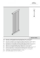
BH Installed height
BL Installed length
BT Overall depth
E
Airvent
G
Weight
H
Distance between mounting studs and inlet/outlet plane
L
Distance between mounting studs
n
Heat-transfer exponent
NA Center-center distance between inlet/outlet fittings
NR Article No.
P
Heat output
P1 Power output of electric heating element
V
Water capacity
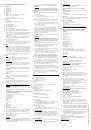
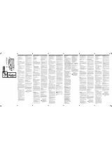
III
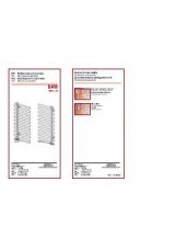
Side and Rear View
E = Bleeder valve or blanking plug
IV
Mounting Points
Plane of inlet/outlet ports
V
Inlet/outlet fittings: 1 ea., equipped with G1/2" internal pipe
threads, both installed with their port facing downward. The inlet
fitting and inlet riser tube are on the left-hand side as standard, but
may be switched to the right-hand side by interchanging riser
tubes and rotating the valves on the lower ends of the riser tubes
through 180°.
Bleeder valve: Equipped with a G1/4" internal pipe thread. May be
installed on the rear of the right-hand or left-hand riser tube.
VI
Max. operating pressure: 10 bar
Pressure tested at: 13 bar
Operating conditions: Circulating hot water at temperatures up to
110 °C. Auxiliary electric heating may be employed. An electric
heating element may be field-retrofitted for this purpose.
VII Note:
If auxiliary electric heating is employed, the safety zones stipulated
under VDE 0100 must be maintained (radiators must be mounted
well away from bathtubs and outside shower stalls, and electrical
outlets and timers must be located at least 0.6 m (24") from the
ends of bathtubs or the enclosures of shower stalls. Installing an
electric heating element will shift the location of the radiator’s inlet
port, since the electric heating elements we supply employ a pipe-
T as an electrical feedthrough.
VIII Note:
If the radiator is to be used on a single-pipe heating system,
remove its riser tube prior to installation. Use a turbolator valve for
connecting the radiator to the heating system.
IX
Intended Uses
These radiators are intended for indoor heating applications and
drying towels, articles of clothing, etc. that have been washed in
water only. Using them for any other purpose is prohibited.
X
Maintenance
Trapped air should be bled out of radiators after they have been placed in
operation and after they have been out of use for extended periods.
XI
Complaints
Contact the installer or a heating contractor if any leaks or other
problems arise.
XII Note:
Installation and repairs should be performed by a heating
contractor only, since failure to observe this requirement will void
the warranty.
XIII Accessories Available
Towel hooks (3), bleeder valves, blanking plugs, pipe-T’s for
installing electric heating elements, electric heating elements
equipped with room thermostats and timers.
This section of the installation instructions should be given to
end users!
1
Read these installation instructions through carefully prior to
installation!
2
Radiators should be shipped and stored in their protective
packagings only!
3
Check the contents of shipping cartons for missing items and
damage immediately upon receipt.
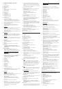
A
Radiator fabricated from circular-cross-section tubing
C
Large-diameter screw
D
Small-diameter screw
E
Large wall insert
F
Small wall insert
G
Spacer
H
Eccentric cap
I
Mounting stud
J
Holder
K
Retaining screw
L
Bleeder valve
M
Blanking plug
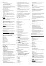
4
Prepare all tools that will be needed.
Ø6 = 6-mm dia., Ø10 = 10-mm dia., Gr.3 = #3 Phillips screwdriver, SW
10 = 10-mm open-end wrench, SW 17 = 17-mm open-end wrench
5
Remove the protective foil from the inlet/outlet fittings and
mounting points only. Leave the rest of the protective foil in place
until the radiator is ready for use.
SW 6 = 6-mm Allen wrench
6
Important
Make certain that bearing strength of the floor wall is sufficient to
support the weight of the radiator! Make certain that all necessary
clearances are maintained. Radiators should be at least 50 mm (2")
distant from walls and ceilings!
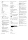
7
Drill two 10-mm-diameter horizontal holes, each 80-mm-deep,
spaced a distance “L” apart, in the wall for the wall inserts.
WARNING!
Exercise extreme caution when drilling any holes in walls!
Make certain that you do not drill into any water, gas, or power
lines! Failure to observe this precaution could lead to fatal
injuries!
Fasten the spacers (G) to the wall using the wall inserts (E) and
screws (C).
SW 6 = 6-mm Allen wrench
8
Rotate the spacers (G) until their top surfaces are level.
SW 10 = 10-mm open-end wrench
9
Slide the eccentric caps (H) onto the mounting studs (I) and screw
the mounting studs (I) into the tapped holes on the rear of the
radiator (A). Make certain that both mounting studs (I) are screwed
in the same distance. Lift the radiator (A) and slide the mounting
studs (I) into the spacers (G).
Gr.3 = #3 Phillips screwdriver
10
Center the holder (J) on the bottom of the third rib from the
bottom. Press the retaining screw (K) into the holder (J) and screw
it in/out until the radiator (A) is parallel to the wall. Mark the spot
where the head of the retaining bold (K) contacts the wall by
drawing a circle around its head with a pencil and then lift the
radiator (A) off the mounting studs (I).
11
Drill a single 6-mm-diameter, 60-mm-deep, hole for a wall insert at
the center of the circle.
WARNING!
Exercise extreme caution when drilling any holes in walls!
Make certain that you do not drill into any water, gas, or power
lines! Failure to observe this precaution could lead to fatal
injuries!
Insert the small wall insert (F) into the drilled hole. Fasten the
retaining screw (K) to the wall using the small-diameter screw (D).
Lift the radiator (A) and hang it on the spacers (G).
SW 17 = 17-mm open-end wrench
12
Screw in the bleeder valve (L) and the blanking plug (M). Align the
holder (J) on the retaining screw (K).
13
Press the holder (J) onto the retaining screw (K). Align the radiator
(A) parallel to the wall by screwing the retaining screw (K) in/out
and then press the eccentric caps (H) into the spacers (G).
These eccentric caps (H) serve as retainers that hold the
radiator in place and prevent its being lifted off the holder (J)!
14
Connect the radiator (A) to the heating pipes using standard,
commercially available, external-thread pipe fittings. Follow the
instructions appearing in Section VIII, above, if the heating system
is of the single-pipe type. Check the entire system for leaks.
15
Put any protective coverings used at the construction site and the
protective foil back on the radiator(A). This protective foil should be
removed before the radiator is placed in service.
16
Dispose of all packaging materials via a recycling system.
Scrapped radiators and their accessories should be to sent to a
recycling plant or disposed of in accordance with local regulations.
Made in Germany • All rights reserved.
Kermi GmbH • Pankofen-Bahnhof 1 • D-94447 Plattling, Germany
Tel.: +49-(0)9931-5010 • FAX: +49-(0)9931-3075 • http://www.kermi.de
Edition: 08/00 • EDP-Code: 6901354
F
Notice de montage Credo-Twist
A
Surface de chauffe
BH Hauteur de construction réelle
BL Longueur de construction réelle
BT Profondeur de construction
E
Purge
G
Poids
H
Ecart entre la fixation et le centre du tuyau de raccordement
L
Ecart entre les perçages
n
Pente
NA Ecart entre les moyeux
NR Numéro d’article
P
Puissance de chauffe
P1 Puissance de chauffe de la résistance électrique
V
Volume d’eau
III
Vue arrière et vue de profil
E = Bouchon purgeur ou bouchon plein
IV
Entraxe
Manchon de raccordement bord inférieur
V
Raccordements
2 x G1/2 (filet intérieur) vers le bas,
Rentrée avec tube injecteur de série à gauche; rentrée à droite possible
en changeant le tube injectuer de côté et en tournant la vanne.
Purge : G1/4 (filet intérieur) vers l’arrière à gauche ou à droite.
VI
Pression de service: max. 10 bar.
Pression de contrôle: 13 bar.
Conditions de service: eau chaude jusqu’à 110 °C.
Fonctionnement mixte possible avec thermoplongeur et raccord en T.
VII Recommandations
En cas de fonctionnement mixte , il faut respecter les secteurs de
protection prescrits dans la norme NF C 15-100 (radiateurs sur le
côté, en dehors du secteur de la baignoire ou de la cabine de douche,
prise de courant et programmateur au moins à 0,6 m sur le côté.
”Lors du montage du thermoplongeur, la position du raccordement
est modifée par la pièce en T.”
VIII Recommandations
En cas de montage monotube, enlevez le tube injecteur du radiateur.
Pour le raccordement au chauffage central, utilisez un répartiteur.
IX
Utilisation autorisée
Le radiateur doit être utilisé uniquement pour chauffer des locaux et
pour sécher des textiles lavés à l’eau.
Toute autre utilisation est non conforme et donc interdite!
X
Entretien
Purgez le radiateur après la mise en service et après chaque période
d’inutilisation prolongée.
XI
Réclamations
En cas de dommages, adressez-vous à votre artisan professionnel.
XII Attention
Faites effectuer le montage et les réparations exclusivement par un artisan
professionnel sinon votre garantie devient caduque!
XIII Accessoires disponibles
- patères porte-serviettes no. 3
- bouchon plein et bouchon purgeur
- thermoplongeur
- raccord en T pour le montage du thermoplongeur
Cette partie de la notice doit être remise au à l’utilisateur final!
1
Avant de procéder à I’installation, veuillez lire attentivement la notice!
2
Transport et stockage uniquement dans l’emballage de protection !
3
Vérifier l’intégralité du contenu de l’emballage et les dommages
éventuels!
A
Radiateur à tuyaux ronds
C
vis, longue
D
vis, courte
E
cheville, longue
F
cheville, courte
G
entretoise
H
capuchon excentrique
I
boulon de suspension
J
support mural
K
boulon à fixation immédiate
L
bouchon de purgeur
M
bouchon plein
Gr. = taille, SW = clé Allène
4
Préparer l’outillage nécessaire.
5
Retirer le film protecteur uniquement au niveaux des points de
raccordement et de montage et laisser le reste sur le radiateur jusqu’à la
mise en service.
SW = clé Allène
6
Important
Vérifiez la force portante du support !
Respectez les cotes radiateur/mur latéral et radiateur/plafond =
min. 50 mm!
7
Percer 2 trous horizontaux pour les chevilles:
Diamètre = 10 mm, profondeur = 80 mm, distance « L ».
Danger de mort !
Lors du perçage, veillez à ne pas endommager des conduites
d’eau, de gaz ou les conduites électriques!
Fixez les entretoises (F) avec les vis (B) et les chevilles (D).
SW = clé Allène
8
Aligner les entretoises horizontalement.
SW = clef Allène
9
Posez les capuchons excentriques (G) sur les boulons de
suspensions (H). Visser les boulons de suspension dans le filetage
sur la face arrière du radiateur. Veillez à la même profondeur de
vissage! Accrochez le radiateur sur les entretoises (F).
Gr. = tournevis
10
Fixez le support mural (I) de façon centrée sur la troisième barre
transversale à partir du bas. Enfoncez le boulon à fixation
immédiate (J) dans le support mural (I) et le réglez-le de manière à
ce que le radiateur soit suspendu verticalement.
Marquez la position du disque du boulon à fixation immédiate (J)
sur le mur. Enlevez à nouveau le radiateur.
11
Percez un trou pour une cheville.
Centre du marquage, diamètre 6 mm, profondeur 60 mm
Danger de mort !
Lors du perçage, veillez à ne pas endommager des conduites
d’eau, de gaz ou les conduites électriques!
Enfoncez la cheville (E) dans le trou percé.
Fixez le boulon à fixation immédiate (J) avec les vis (C).
Accrochez le radiateur (A) sur les entretoises (F).
SW = clef Allène
12
Vissez le bouchon purgeur (K) et le bouchon plein (L).
Accrochez le radiateur.
13
Poussez le support mural (I) sur le boulon à fixation immédiate (I).
Alignez le radiateur verticalement, à cet effet, réglez le boulon à
fixation immédiate. Enfoncez les capuchons excentriques (G) dans
les entretoises (F).
Le capuchon excentrique est une sécurité pour la suspension !
14
Raccordez le radiateur à la conduite d’eau au moyen d’un raccord par vis
extérieur que l’on trouve dans le commerce. (Radiateur à un seul tuyau:
veuillez tenir compte du point VIII!) Vérifiez l’étanchéité de l’installation!
15
Remettre complètement le film protecteur sur le radiateur. Ne le retirer
que lors de la mise en service!
16
Eliminez les emballages via les systèmes de recyclage adaptés. Déposez
les vieux radiateurs et les accessoires dans un centre de recyclage, ou
une décharge officielle en respectant les prescriptions locales.
Made in Germany • All rights reserved.
Kermi GmbH • Pankofen-Bahnhof 1 • D-94447 Plattling / Germany
Téléphone +49+9931/501-0 • Télécopie +49+9931/3075
http://www.kermi.de
Edition 08/00 • N° informatique 6901357
A
usgabe 05/04 ED
V
-Nr
. 6901576