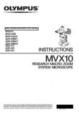
MVX10
CONTENTS
IMPORTANT
— Be sure to read this section for safe use of the equipment. —
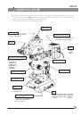
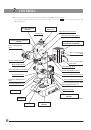
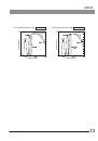
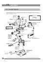
1 NOMENCLATURE
2 CONTROLS
3
4 OPERATION
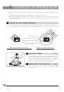
SUMMARY OF REFLECTED FLUORESCENT LIGHT OBSERVATION PROCEDURE
4-1 Base
.......................................................................................................................................................................................................................
10
4-2 Microscope Body and Focusing Assembly
........................................................................................
10, 11
4-3 Coaxial Fluorescence Illuminator
.......................................................................................................................
12-15
4-4 Observation Tube
......................................................................................................................................................................
15-17
1
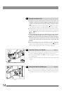
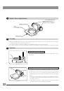
Using the Stage Plate
2
Placing the Specimen
1-4
Correct assembly and adjustments are indispensable for the microscope to manifest its full performance. If you
want to assemble the microscope by yourself, refer to Chapter 11, “ASSEMBLY” before other chapters. (P. 36 to P. 44)
5 TV OBSERVATION AND PHOTOMICROGRAPHY
18, 19
5
6, 7
8, 9
10-17
1
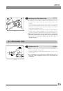
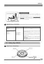
Adjusting the Focus
2
Adjusting the Rotation Tension of the Coarse Focus Adjustment Knob
3
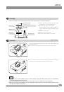
Engaging and Disengaging the Zooming Knob Click Stop Position
4
Adjusting the Aperture Iris Diaphragm
5
Using the Objective Correction Collar
1
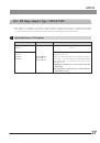
Selecting the Fluorescence Mirror Unit
2
Turning the Burner ON
3
Opening/Closing the Shutter
4
Using the Field Iris Diaphragm
5
Switching the Filter Slider Knob
1
Adjusting the Tilt
2
Adjusting the Interpupillar Distance
3
Adjusting the Diopter (Zoom Parfocality Adjustment)
4
Using the Eye Shades
5
Using the Eyepiece Micrometer Disk
6
Selecting the Light Path
7
Switching the Monaural/Stereo View
1
Selecting the C-Mount Adapter Magnification
2
Attaching the C-Mount Adapter
3
Selecting the TV Camera Light Path
4
Adjusting the Parfocality Between Observation Image and Monitor Image