3
MVX10
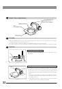
1. To clean the lenses and other glass components, simply blow dirty away using a commercially available blower and
wipe gently using a piece of cleaning paper (or clean Gauze).
If a lens is strained with fingerprints or oil smudges, wipe it gauze slightly moistened with commercially available
absolute alcohol.
Since the absolute alcohol is highly flammable, it must be handled carefully.
Be sure to keep it away from open flames or potential sources of electrical sparks - for example, eletrical equip-
ment that is being switched on or off.
Also remember to always use it only in a well-ventilated room.
2. The equipment uses plastic resins extensively in its external finish. Do not attempt to use organic solvents to clean the
non-optical components of the microscope. To clean these components, use a lint-free, soft cloth lightly moistened with
a diluted neutral detergent.
3. Never disassemble any part of the microscope as this could result in malfunctions or reduced performance.
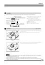
4. When not using the microscope, keep it covered with the dust cover provided. Ensure that the lamp housing is cool
before covering the microscope.
5. When the hour counter on the power supply unit indicates 300 hours (USH-103OL, HBO103W/2), set the main switch
to “ ” (OFF) for safety, wait for more than 10 minutes and then replace the burner (see page 42). Unlike the fluorescent
lamps, the mercury burner seals high-pressure gas inside. If it used after the specified service life has been exceeded,
the glass tube may be distorted accumulatively and may eventually burst, though this happens very rarely. The used
mercury burner should be disposed of as an industrial waste. If you cannot dispose of it properly, contact Olympus.
6. When disposing of the microscope. Check the regulations and rules of your local government and be sure to observe
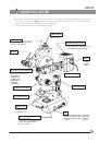
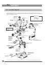
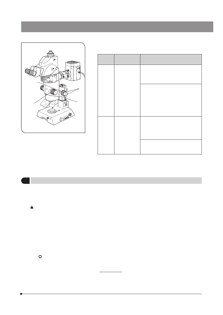
them. To dispose of only the gas spring (|, Fig. 2) used in the counterbalance of the focusing assembly, follow the
precautions provided with the gas spring.
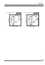
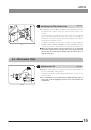
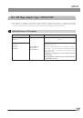
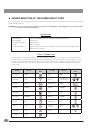
6. Observe the following cautions when operating the coarse focus
adjustment knobs or the zooming knobs.
1. If the knob hits the upper or lower lim-
iting mechanism violently or it is rotated
after it hits a limiting mechanism, the
internal mechanism may be damaged.
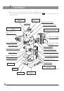
Fig. 2
Operation
Manipulated
Controls
Caution
Focusing
Coarse focus
adjustment
knobs @ (Fig. 2)
2. If the knobs on the left and right are
rotated in opposite directions, the in-
ternal mechanism will be damaged.
(The rotation tension of the knob
should be adjusted using the rotation
tension adjustment ring ³ on the
knob. See page 10.)
Zooming knobs
² (Fig. 2)
1. If the knob hits the upper or lower lim-
iting mechanism violently or it is rotated
after it has hit a limiting mechanism,
the internal mechanism may be dam-
aged.
2. If the knobs on the left and right are
rotated in opposite directions, the inter-
nal mechanism will be damaged.
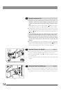
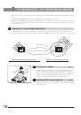
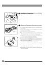
7. Before moving the microscope, detach the modules including the tilting
trinocular head and lamp housing to reduce the total weight. Then hold
it by the base, not by the zoom microscope body.
Zooming
@
²
³
2
Maintenance and Storage
|