10
EN
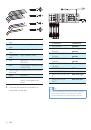
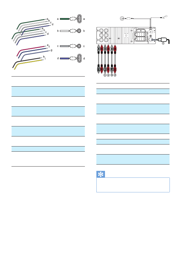
1 Green/black
strip
Left speaker (Rear)
2 White/black
strip
Left speaker (Front)
3 Gray/black
strip
Right speaker (Front)
4 Purple/black
strip
Right speaker (Rear)
e Red
Ignition key +12V DC when
ON/ACC
f
Blue
Motor/electric antenna relay
control lead
g White-edged
blue strip
Amplifier relay control lead
h Black
Ground
i
Yellow
To the +12V car battery
which is energized at all
times
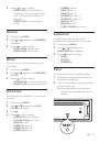
3
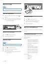
Connect the antenna and amplifier as
illustrated, if applicable.
Connector
Connect to
1 ANTENNA
Antenna
2 FRONT LINE OUT R
(Socket)
Front right
speaker
3 FRONT LINE OUT L
(Socket)
Front left
speaker
4 REAR LINE OUT R
(Socket)
Rear right
speaker
5 REAR LINE OUT L
(Socket)
Rear left speaker
6 OE REMOTE (Purple)
OE Remote
7 SUBWOOFER (Blue)
Subwoofer
8 REAR AUX LINE OUT
R
Rear Aux right
9 REAR AUX LINE
OUT L
Rear Aux left
Tip
•
The pin arrangement for the ISO connectors depends
on the type of vehicle you drive. Be sure to make
proper connections to prevent damage to the unit.
f
g
h
i